Toshiba MW27F51 Service Manual - Page 50
: Confirmation of Fixed Value step No., FUNCTION, 19: SUB CONTRAST MAX, Fig. 1-1, 18: COLOR CENTER
 |
View all Toshiba MW27F51 manuals
Add to My Manuals
Save this manual to your list of manuals |
Page 50 highlights
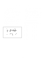
ELECTRICAL ADJUSTMENTS 2-18: COLOR CENTER 1. Receive the color bar pattern. (RF Input) 2. Using the remote control, set the brightness, contrast, color and tint to normal position. 3. Connect the oscilloscope to TP804. 4. Activate the adjustment mode display of Fig. 1-1 and press the channel button (23) on the remote control to select "COL CENT". 5. Adjust the VOLTS RANGE VARIABLE knob of the oscilloscope until the range between white 100% and 0% is set to 4 scales on the screen of the oscilloscope. 6. Press the VOL. UP/DOWN button on the remote control until the red color level is adjusted to 110 ± 5% of the white level. (Refer to Fig. 2-5) 7. Receive the color bar pattern. (Audio Video Input) 8. Press the INPUT button on the remote control to set to the AV mode. Then perform the above adjustments 2~6. 9. Press the DVD button on the remote control to set to the DVD mode. 10. Activate the adjustment mode display of Fig. 1-1 and press the channel button (23) on the remote control to select "COL CENT". 11. Press the VOL. UP/DOWN button on the remote control to set the same step numbers as the AV mode. White 0% 100% White 100% Red Level Fig. 2-5 2-19: SUB CONTRAST MAX 1. Activate the adjustment mode display of Fig. 1-1 and press the channel button (21) on the remote control to select "CONT MAX". 2. Press the VOL. UP/DOWN button on the remote control until the contrast step No. becomes "95". 3. Receive a broadcast and check if the picture is normal. 4. Press the INPUT button on the remote control to set to the AV mode. Then perform the above adjustments 1~3. 5. Receive a broadcast and check if the picture is normal. Press the DVD button on the remote control to set to the DVD mode. 6. Activate the adjustment mode display of Fig. 1-1 and press the channel button (21) on the remote control to 7. select "CONT MAX". 8. Press the VOL. UP/DOWN button on the remote control to set the same step numbers as the AV mode. 2-20: Confirmation of Fixed Value (step No.) Please check if the fixed values of the each adjustment items are set correctly referring below. NO. FUNCTION 01 OSD C 04 H.BLK L 05 H.BLK R 07 V.POSI 09 VS.CORR 10 V.COMP 18 BRI MAX 19 BRI MIN 20 CONT CENT 22 CONT MIN 24 COL MAX 25 COL MIN 27 SHARP 28 SUB BIAS 34 H.COMP 35 T.STE 38 H.FREQ RF AV DVD 02 02 02 04 04 04 03 03 03 02 02 02 18 18 18 03 03 03 45 45 45 05 05 05 70 70 70 15 15 15 127 127 127 00 00 00 25 25 25 00 00 00 02 02 02 00 00 00 03 03 03 D3-4
-
 1
1 -
2
-
3
-
4
-
5
-
6
-
7
-
8
-
9
-
10
-
11
-
12
-
13
-
14
-
15
-
16
-
17
-
18
-
19
-
20
-
21
-
22
-
23
-
24
-
25
-
26
-
27
-
28
-
29
-
30
-
31
-
32
-
33
-
34
-
35
-
36
-
37
-
38
-
39
-
40
-
41
-
42
-
43
-
44
-
 45
45 -
 46
46 -
 47
47 -
 48
48 -
 49
49 -
 50
50 -
 51
51 -
 52
52 -
 53
53 -
 54
54 -
 55
55 -
56
-
57
-
58
-
59
-
60
-
61
-
62
-
63
-
64
-
65
-
66
-
67
-
68
-
69
-
70
-
71
-
72
-
73
-
74
-
75
-
76
-
77
-
78
-
79
-
80
-
81
-
82
-
83
-
84
-
85
-
86
-
87
-
88
-
89
-
90
-
91
-
92
-
93
-
94
-
95
-
96
-
97
-
98
-
99
-
100
-
101
-
102
-
103
-
104
-
105
-
106
-
107
-
108
-
109
-
110
 |
 |
