Toshiba MW27F51 Service Manual - Page 48
Toshiba MW27F51 Manual
 |
View all Toshiba MW27F51 manuals
Add to My Manuals
Save this manual to your list of manuals |
Page 48 highlights
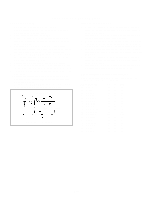
ELECTRICAL ADJUSTMENTS (TV SECTION) 2-2: CONSTANT VOLTAGE 1. Place the set in AV MODE without signal. 2. Using the remote control, set the brightness and contrast to normal position. 3. Connect the digital voltmeter to TP401. 4. Adjust the VR1701 until the digital voltmeter is 135.5 ± 0.5V. 2-3: CUT OFF 1. Adjust the unit to the following settings. R.BIAS=127, G.BIAS=127, B.BIAS=127, R.DRV=63, G.DRV=07, B.DRV=63, 2. Place the set in Aging Test for more than 15 minutes. 3. Place the set in AV MODE without signal. 4. Using the remote control, set the brightness and contrast to normal position. 5. Activate the adjustment mode display of Fig. 1-1 and press the channel button (02) on the remote control to select "CUT OFF". 6. Adjust the Screen Volume until a dim raster is obtained. 2-7: HORIZONTAL SIZE 1. Receive the monoscope pattern. 2. Using the remote control, set the brightness and contrast to normal position. 3. Activate the adjustment mode display of Fig. 1-1 and press the channel button (29) on the remote control to select "H. SIZE". 4. Press the VOL. UP/DOWN button on the remote control until the SHIFT quantity of the OVER SCAN on right and left becomes 10 ± 2%. 2-8: VERTICAL POSITION 1. Receive the monoscope pattern. 2. Using the remote control, set the brightness and contrast to normal position. 3. Activate the adjustment mode display of Fig. 1-1 and press the channel button (07) on the remote control to select "V.POSI". 4. Check if the step No. V.POSI is "02". 5. Adjust the VR404 until the horizontal line becomes fit to the notch of the shadow mask. (Refer to Fig. 2-2) 2-4: WHITE BALANCE NOTE: Adjust after performing CUT OFF adjustment. 1. Place the set in Aging Test for more than 15 minutes. 2. Receive the gray scale pattern from the Pattern Generator. 3. Using the remote control, set the brightness and contrast to normal position. 4. Activate the adjustment mode display of Fig. 1-1 and press the channel button (11) on the remote control to select "R.BIAS". 5. Press the CH. UP/DOWN button on the remote control to select the "R.BIAS", "G.BIAS", "B.BIAS", "R.DRV", "B.DRV" or "G.DRV". 6. Adjust the VOL. UP/DOWN button on the remote control to whiten the R.BIAS, G.BIAS, B.BIAS, R.DRV, B.DRV, and G.DRV at each step tone sections equally. 7. Perform the above adjustments 5 and 6 until the white color is achieved. 2-5: FOCUS 1. Receive the monoscope pattern. 2. Turn the Focus Volume fully counterclockwise once. 3. Adjust the Focus Volume until picture is distinct. horizontal line Notch Shadow mask Fig. 2-2 2-9: VERTICAL SIZE 1. Receive the monoscope pattern. 2. Using the remote control, set the brightness and contrast to normal position. 3. Activate the adjustment mode display of Fig. 1-1 and press the channel button (06) on the remote control to select "V.SIZE". 4. Press the VOL. UP/DOWN button on the remote control until the Up/Down OVER SCAN Quantity becomes equal to the Right/Left OVER SCAN Quantity. 2-6: HORIZONTAL POSITION 1. Receive the monoscope pattern. 2. Using the remote control, set the brightness and contrast to normal position. 3. Activate the adjustment mode display of Fig. 1-1 and press the channel button (03) on the remote control to select "H.POSI". 4. Press the VOL. UP/DOWN button on the remote control until the SHIFT quantity of the OVER SCAN on right and left becomes minimum. 2-10: VERTICAL LINEARITY NOTE: Adjust after performing adjustments in section 2-9. After the adjustment of Vertical Linearity, reconfirm the Vertical Position and Vertical Size adjustments. 1. Receive the monoscope pattern. 2. Using the remote control, set the brightness and contrast to normal position. 3. Activate the adjustment mode display of Fig. 1-1 and press the channel button (08) on the remote control to select "V.LIN". 4. Press the VOL. UP/DOWN button on the remote control until the SHIFT quantity of the OVER SCAN on upside and downside becomes minimum. D3-2
-
 1
1 -
2
-
3
-
4
-
5
-
6
-
7
-
8
-
9
-
10
-
11
-
12
-
13
-
14
-
15
-
16
-
17
-
18
-
19
-
20
-
21
-
22
-
23
-
24
-
25
-
26
-
27
-
28
-
29
-
30
-
31
-
32
-
33
-
34
-
35
-
36
-
37
-
38
-
39
-
40
-
41
-
42
-
 43
43 -
 44
44 -
 45
45 -
 46
46 -
 47
47 -
 48
48 -
 49
49 -
 50
50 -
 51
51 -
 52
52 -
 53
53 -
54
-
55
-
56
-
57
-
58
-
59
-
60
-
61
-
62
-
63
-
64
-
65
-
66
-
67
-
68
-
69
-
70
-
71
-
72
-
73
-
74
-
75
-
76
-
77
-
78
-
79
-
80
-
81
-
82
-
83
-
84
-
85
-
86
-
87
-
88
-
89
-
90
-
91
-
92
-
93
-
94
-
95
-
96
-
97
-
98
-
99
-
100
-
101
-
102
-
103
-
104
-
105
-
106
-
107
-
108
-
109
-
110
 |
 |
