Toshiba MW27F51 Service Manual - Page 49
: Corner Corr Top - white lines
 |
View all Toshiba MW27F51 manuals
Add to My Manuals
Save this manual to your list of manuals |
Page 49 highlights
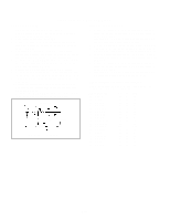
ELECTRICAL ADJUSTMENTS 2-11: TRAPEZIUM 1. Receive the crosshatch signal from the Pattern Generator. 2. Using the remote control, set the brightness and contrast to normal position. 3. Activate the adjustment mode display of Fig. 1-1 and press the channel button (31) on the remote control to select "TRAPEZIUM". 4. Press the VOL. UP/DOWN button on the remote control until the both vertical lines of the screen become parallel. 2-12: PARABOLA 1. Receive the crosshatch signal from the Pattern Generator. 2. Using the remote control, set the brightness and contrast to normal position. 3. Activate the adjustment mode display of Fig. 1-1 and press the channel button (30) on the remote control to select "PARABOLA". 4. Press the VOL. UP/DOWN button on the remote control until the right and left vertical lines are straight. 2-13: CORNER CORR TOP 1. Receive the crosshatch signal from the Pattern Generator. 2. Using the remote control, set the brightness and contrast to normal position. 3. Activate the adjustment mode display of Fig. 1-1 and press the channel button (32) on the remote control to select "COR TOP". 4. Press the VOL. UP/DOWN button on the remote control until the upper section of the both ends vertical lines are straight. 2-14: CORNER CORR BOTTOM 1. Receive the crosshatch signal from the Pattern Generator. 2. Using the remote control, set the brightness and contrast to normal position. 3. Activate the adjustment mode display of Fig. 1-1 and press the channel button (33) on the remote control to select "COR BTM". 4. Press the VOL. UP/DOWN button on the remote control until the bottom section of the both ends vertical lines are straight. 2-16: BRIGHT CENTER 1. Receive the monoscope pattern. (RF Input) 2. Using the remote control, set the brightness and contrast to normal position. 3. Activate the adjustment mode display of Fig. 1-1 and press the channel button (17) on the remote control to select "BRI CENT". 4. Press the VOL. UP/DOWN button on the remote control until the white 15% is starting to be visible 5. Receive the monoscope pattern. (Audio Video Input) 6. Press the INPUT button on the remote control to set to the AV mode. Then perform the above adjustments 2~4. 7. Press the DVD button on the remote control to set to the DVD mode. 8. Activate the adjustment mode display of Fig. 1-1 and press the channel button (17) on the remote control to select "BRI CENT". 9. Press the VOL. UP/DOWN button on the remote control to set the same step numbers as the AV mode. 2-17: TINT 1. Receive the color bar pattern. (RF Input) 2. Using the remote control, set the brightness, contrast, color and tint to normal position. 3. Connect the oscilloscope to TP806. 4. Activate the adjustment mode display of Fig. 1-1 and press the channel button (26) on the remote control to select "TINT". 5. Press the VOL. UP/DOWN button on the remote control until the section "A" becomes a straight line (Refer to Fig. 2-4). 6. Receive the color bar pattern. (Audio Video Input) 7. Press the INPUT button on the remote control to set to the AV mode. Then perform the above adjustments 2~5. Press the DVD button on the remote control to set to the 8. DVD mode. Activate the adjustment mode display of Fig. 1-1 and 9. press the channel button (26) on the remote control to select "TINT". 10. Press the VOL. UP/DOWN button on the remote control to set the same step numbers as the AV mode. 2-15: OSD HORIZONTAL 1. Activate the adjustment mode display of Fig. 1-1. 2. Press the VOL. UP/DOWN button on the remote control until the difference of A and B becomes minimum. (Refer to Fig. 2-3) TV 00 OSD A 07 B Fig. 2-3 D3-3 "A" Fig. 2-4
-
 1
1 -
2
-
3
-
4
-
5
-
6
-
7
-
8
-
9
-
10
-
11
-
12
-
13
-
14
-
15
-
16
-
17
-
18
-
19
-
20
-
21
-
22
-
23
-
24
-
25
-
26
-
27
-
28
-
29
-
30
-
31
-
32
-
33
-
34
-
35
-
36
-
37
-
38
-
39
-
40
-
41
-
42
-
43
-
 44
44 -
 45
45 -
 46
46 -
 47
47 -
 48
48 -
 49
49 -
 50
50 -
 51
51 -
 52
52 -
 53
53 -
 54
54 -
55
-
56
-
57
-
58
-
59
-
60
-
61
-
62
-
63
-
64
-
65
-
66
-
67
-
68
-
69
-
70
-
71
-
72
-
73
-
74
-
75
-
76
-
77
-
78
-
79
-
80
-
81
-
82
-
83
-
84
-
85
-
86
-
87
-
88
-
89
-
90
-
91
-
92
-
93
-
94
-
95
-
96
-
97
-
98
-
99
-
100
-
101
-
102
-
103
-
104
-
105
-
106
-
107
-
108
-
109
-
110
 |
 |
