Toshiba Tecra A8 Maintenance Manual
Toshiba Tecra A8 Manual
 |
View all Toshiba Tecra A8 manuals
Add to My Manuals
Save this manual to your list of manuals |
Toshiba Tecra A8 manual content summary:
- Toshiba Tecra A8 | Maintenance Manual - Page 1
Toshiba Personal Computer TECRA A8 series / Satellite Pro A120 series Maintenance Manual TOSHIBA CORPORATION File Number 960-573 [CONFIDENTIAL] - Toshiba Tecra A8 | Maintenance Manual - Page 2
. Toshiba Personal Computer TECRA A8 series / Satellite Pro A120 series Maintenance Manual First edition June 2006 Disclaimer The information presented in this manual has been reviewed and validated for accuracy. The included set of instructions and descriptions are accurate for the TECRA A8 series - Toshiba Tecra A8 | Maintenance Manual - Page 3
or fire. ‰ If you replace the battery pack or RTC battery, be sure to use only the same model battery or an equivalent battery recommended by Toshiba. Installation of the wrong battery can cause the battery to explode. TECRA A8 /Satellite Pro A120 Maintenance Manual (960-573) [CONFIDENTIAL] iii - Toshiba Tecra A8 | Maintenance Manual - Page 4
and replacement of the FRUs. Appendices The appendices describe the following: ‰ Handling the LCD module ‰ Board layout ‰ Pin assignments ‰ Keyboard scan/character codes ‰ Key layout ‰ Wiring diagrams ‰ BIOS rewrite procedures ‰ EC/KBC rewrite procedures ‰ Reliability iv [CONFIDENTIAL] TECRA A8 - Toshiba Tecra A8 | Maintenance Manual - Page 5
input Text that you are instructed to type in is shown in the boldface type below: DISKCOPY A: B: The display Text generated by the computer that appears on its display is presented in the type face below: Format complete System transferred TECRA A8 /Satellite Pro A120 Maintenance Manual (960-573 - Toshiba Tecra A8 | Maintenance Manual - Page 6
inch Hard Disk Drive 1-14 1.3 Keyboard...1-16 1.4 Optical Drive...1-17 1.5 TFT Color Display 1-21 1.6 Power Supply ...1-24 1.7 Batteries ...1-28 1.8 AC Adaptor...1-30 Chapter 2 Troubleshooting Procedures 2.1 Troubleshooting ...2-1 2.2 Troubleshooting Flowchart 2-3 2.3 Power Supply Troubleshooting - Toshiba Tecra A8 | Maintenance Manual - Page 7
3.24 Floppy Disk Drive Utilities 3-51 3.25 System Configuration 3-56 3.26 Wireless LAN Test Program (Atheros 3-58 3.27 Wireless LAN Test Program (Intel-made b/g, a/b/g 3-65 3.28 LAN/Modem/Bluetooth/IEEE1394 Test Program 3-69 3.29 Sound Test program 3-84 3.30 SETUP ...3-90 TECRA A8 /Satellite - Toshiba Tecra A8 | Maintenance Manual - Page 8
24 PC card slot ...4-56 4.25 LCD unit/FL inverter 4-57 4.26 Cover latch ...4-62 4.27 Display rear cover ...4-63 4.28 Wireless LAN antenna/Bluetooth antenna 4-65 4.29 Hinge...4-71 4.30 Speaker...4-73 4.31 Fluorescent Lamp...4-77 viii [CONFIDENTIAL] TECRA A8 /Satellite Pro A120 Maintenance Manual - Toshiba Tecra A8 | Maintenance Manual - Page 9
C Pin Assignments C-1 Appendix D Keyboard Scan/Character Codes D-1 Appendix E Key Layout...E-1 Appendix F Wiring Diagrams F-1 Appendix G BIOS rewrite Procedures G-1 Appendix H EC/KBC rewrite Procedures H-1 Appendix I Reliability...I-1 TECRA A8 /Satellite Pro A120 Maintenance Manual (960-573 - Toshiba Tecra A8 | Maintenance Manual - Page 10
x [CONFIDENTIAL] TECRA A8 /Satellite Pro A120 Maintenance Manual (960-573) - Toshiba Tecra A8 | Maintenance Manual - Page 11
Chapter 1 Hardware Overview [CONFIDENTIAL] - Toshiba Tecra A8 | Maintenance Manual - Page 12
1 Hardware Overview 1-ii [CONFIDENTIAL] TECRA A8 /Satellite Pro A120 Maintenance Manual (960-573) - Toshiba Tecra A8 | Maintenance Manual - Page 13
DVD-Super Multi Drive 1-20 1.5 TFT Color Display 1-21 1.5.1 LCD Module 1-21 1.5.2 FL Inverter Board 1-23 1.6 Power Supply...1-24 1.7 Batteries...1-28 1.7.1 Main Battery 1-28 1.7.2 RTC battery 1-29 1.8 AC Adaptor ...1-30 TECRA A8 /Satellite Pro A120 Maintenance Manual (960-573) [CONFIDENTIAL - Toshiba Tecra A8 | Maintenance Manual - Page 14
supply output rating (ATI chipset model 1-26 Battery specifications 1-28 Time required for charges 1-28 Data preservation time 1-29 RTC battery charging/data preservation time 1-29 AC adapter specifications 1-30 1-iv [CONFIDENTIAL] TECRA A8 /Satellite Pro A120 Maintenance Manual (960-573) - Toshiba Tecra A8 | Maintenance Manual - Page 15
with ATI RC420MB or Intel 945GM as North Bridge, ATI SB450 or Intel ICH7-M as South Bridge and Texas Instrument PCI7412 as Card Controller. ‰ VGA Controller An internal Graphics Controller in North Bridge is used. TECRA A8 /Satellite Pro A120 Maintenance Manual (960-573) [CONFIDENTIAL] 1-1 - Toshiba Tecra A8 | Maintenance Manual - Page 16
control of the on-screen pointer and scrolling of windows. ‰ Batteries The computer has two batteries: a rechargeable Lithium-Ion main battery pack and RTC battery (that backs up the Real Time Clock and CMOS memory). 1-2 [CONFIDENTIAL] TECRA A8 /Satellite Pro A120 Maintenance Manual (960-573) - Toshiba Tecra A8 | Maintenance Manual - Page 17
who has registered his/her fingerprint to use the computer. ‰ Sound system The sound system is equipped with the following features: • Stereo speakers • Volume control • Stereo headphone jack • External microphone jack TECRA A8 /Satellite Pro A120 Maintenance Manual (960-573) [CONFIDENTIAL] 1-3 - Toshiba Tecra A8 | Maintenance Manual - Page 18
TOSHIBA Assist button When this button is pressed during power-on, the computer is connected to "Toshiba Assist". When this button is pressed during power-off, the computer is turned on and connected to "Toshiba Assist". 1-4 [CONFIDENTIAL] TECRA A8 /Satellite Pro A120 Maintenance Manual (960-573) - Toshiba Tecra A8 | Maintenance Manual - Page 19
1.1 Features The front of the computer is shown in figure 1-1. 1 Hardware Overview Figure 1-1 Front of the computer TECRA A8 /Satellite Pro A120 Maintenance Manual (960-573) [CONFIDENTIAL] 1-5 - Toshiba Tecra A8 | Maintenance Manual - Page 20
1 Hardware Overview The system unit configuration is shown in figure 1-2. 1.1 Features Figure 1-2 System unit configuration 1-6 [CONFIDENTIAL] TECRA A8 /Satellite Pro A120 Maintenance Manual (960-573) - Toshiba Tecra A8 | Maintenance Manual - Page 21
1.1 Features Figure 1-3-1, 1-3-2 is a block diagram of the system unit. 1 Hardware Overview Figure 1-3-1 System unit block diagram (Intel chipset model) Figure 1-3-2 System unit block diagram (ATI chipset model) TECRA A8 /Satellite Pro A120 Maintenance Manual (960-573) [CONFIDENTIAL] 1-7 - Toshiba Tecra A8 | Maintenance Manual - Page 22
46GHz (410) 1.60GHz (420) 1.72GHz (430) - Integrated L1 cache memory of 64KB (32KB +32KB) - Integrated L2 cache memory of 1MB - Processor bus speed: 533MHz - Core voltage: Multiple VID - 478-pin Micro FC-PGA package 1-8 [CONFIDENTIAL] TECRA A8 /Satellite Pro A120 Maintenance Manual (960-573) - Toshiba Tecra A8 | Maintenance Manual - Page 23
Integrated GFX Core (250MHz) - DMI(Direct Media Interface) - Supports ICH. - 1466-ball 37.5×37.5×2.56mm FC-BGA package • ATI RC420MD: - Graphic controller - System Memory controller : DDR2-400/DDR2-533/DDR2-667, 2GB(max) TECRA A8 /Satellite Pro A120 Maintenance Manual (960-573) [CONFIDENTIAL] 1-9 - Toshiba Tecra A8 | Maintenance Manual - Page 24
66/33) - AC'97 2.3 codecs ACPI 2.0 compliant − Enhanced DMA Controller, Interrupt Controller, and Timer Functions − Integrated Serial ATA Host Controller (4 ports) − Integrated IDE controller supports Ultra ATA 100/66/33 (2 ports) 1-10 [CONFIDENTIAL] TECRA A8 /Satellite Pro A120 Maintenance Manual - Toshiba Tecra A8 | Maintenance Manual - Page 25
FHW) interface support − Alert On LAN (AOL) − Package 564 pin BGA (31 x 31mm) ‰ PC Card Controller (TI PCI7412) − PCI I/F − CardBus / Ultra media Controller (1 socket) − SD/MMC, Memory Stick, XD Card Controller − 1394 Controller (2 ports) - 288-ball, 16×16×1.4mm, BGA Package TECRA A8 /Satellite Pro - Toshiba Tecra A8 | Maintenance Manual - Page 26
− Stereo headphone jack − External microphone jack ‰ Modem Controller • Askey-made one MDC is used. • This controller has the following functions: - One RJ11 port - V.92 (V.90) 56K Modem/FAX - Supports Ring Wakeup 1-12 [CONFIDENTIAL] TECRA A8 /Satellite Pro A120 Maintenance Manual (960-573) - Toshiba Tecra A8 | Maintenance Manual - Page 27
Intel Vidaria Ethernet/Fast Ethernet: ReaLTek RTL 8100CL - One RJ45 port - Supports WOL - Supports LED ‰ Wireless LAN • Intel made or Askey made wireless LAN card in the PCI Express Mini card slot − Supports 802.11b/g or 802.11a/b/g − Supports Wireless Communication SW − Supports WEP − Supports WOL - Toshiba Tecra A8 | Maintenance Manual - Page 28
Hard Disk Drive 1.2 2.5-inch Hard Disk Drive The removable HDD is a random access non-volatile storage device. It has a non-removable 2.5-inch magnetic disk and mini-Winchester type magnetic heads. The computer supports 1-14 [CONFIDENTIAL] TECRA A8 /Satellite Pro A120 Maintenance Manual (960-573) - Toshiba Tecra A8 | Maintenance Manual - Page 29
1.2 2.5-inch Hard Disk Drive 1 Hardware Overview Table 1-1 2.5-inch HDD specifications (2/2) Items Outline dimensions Width (mm) Height (mm) Depth MB/s max 1.5 8,192 12 typ 4 typ. 629 Mb/s max. 1.5 8,192 10 typ. TECRA A8 /Satellite Pro A120 Maintenance Manual (960-573) [CONFIDENTIAL] 1-15 - Toshiba Tecra A8 | Maintenance Manual - Page 30
control key. The keyboard is connected to membrane connector on the system board and controlled by the keyboard controller. Figure 1-5 is a view of the keyboard. See Appendix E about a layout of the keyboard. Figure 1-5 Keyboard 1-16 [CONFIDENTIAL] TECRA A8 /Satellite Pro A120 Maintenance Manual - Toshiba Tecra A8 | Maintenance Manual - Page 31
.7(excluding projections) 129.4 (excluding projections) 165 or less Max. 24x CAV 33.3Mbytes/sec max. 1,545 -3,600kB/sec 110 typ. CD: CD/CD-ROM (12cm, 8cm), CD-R, CD-RW CD: CD-DA, CD-ROM, CD-ROM XA, PHOTO CD, Enhanced CD TECRA A8 /Satellite Pro A120 Maintenance Manual (960-573) [CONFIDENTIAL] 1-17 - Toshiba Tecra A8 | Maintenance Manual - Page 32
DVD-RAM, DVD+R, DVD+RW CD: CD-DA, CD-ROM, CD-ROM XA, PHOTO CD, Enhanced CD, CD-text, Multi-session, Addressing method 2 DVD: DVD-ROM, DVD-R, DVD-RW,DVDVideo, DVD-R/RW(Single/Multi-session, Packet), DVD-RAM (2.6GB/4.7GB) 1-18 [CONFIDENTIAL] TECRA A8 /Satellite Pro A120 Maintenance Manual (960-573) - Toshiba Tecra A8 | Maintenance Manual - Page 33
time (ms) CD-ROM DVD-ROM Supported Formats Specifications MATSUSHITA G8CC0002J520 ROM (12cm,8cm), CD-R, CDRW, CD-DA, CD-ROM XA, Photo CD, CD-Extra(CD+), CD-text DVD: DVD-ROM, DVD-R, DVD-RW (Ver1.2), DVD-Video, DVD+R, DVD+RW, DVD-RAM (2.6GB/4.7GB) TECRA A8 /Satellite Pro A120 Maintenance Manual - Toshiba Tecra A8 | Maintenance Manual - Page 34
CD-ROM (12cm, 8cm), CD-R, CD-RW DVD: DVD-ROM, DVD-R, DVD-RW, DVD-RAM, DVD+RW CD: CD-DA, CD-ROM, CD-ROM XA, PHOTO CD, CD-Extra(CD+), CD-text DVD: DVD-R, DVD-RW (Ver. 1.1, 1.2), DVD-Video, DVD+R, DVD+RW, DVD-RAM (2.6GB/4.7GB) 1-20 [CONFIDENTIAL] TECRA A8 /Satellite Pro A120 Maintenance Manual (960 - Toshiba Tecra A8 | Maintenance Manual - Page 35
support displays simultaneously. Figure 1-6 shows a view of the LCD module and Table 1-6 lists the specifications. Figure 1-6 LCD module Table 1-6 LCD (V) 331.2(H) x 207.0(V) Table 1-6 LCD module specifications (2/2) TECRA A8 /Satellite Pro A120 Maintenance Manual (960-573) [CONFIDENTIAL] 1-21 - Toshiba Tecra A8 | Maintenance Manual - Page 36
WXGA TFT (SAMSUNG G33C0003F110) 1,280(W) x 800(H) 0.258(H) x 0.258(V) 331.2(H) x 207.0(V) Specifications 15.4inch WXGA TFT (SAMSUNG G33C0003H110) 1,280(W) x 800(H) 0.258(H) x 0.258(V) 331.2(H) x 207.0(V) 1-22 [CONFIDENTIAL] TECRA A8 /Satellite Pro A120 Maintenance Manual (960-573) - Toshiba Tecra A8 | Maintenance Manual - Page 37
the LCD module. Table 1-7 lists the FL inverter board specifications. Table 1-7 FL inverter board specifications Input Output Item Voltage (VDC) Power (W) Voltage (Vrms) Current (mArms) Power (W/VA) Specifications G71C00011221 5 7 750 6.0 5/7 TECRA A8 /Satellite Pro A120 Maintenance Manual (960 - Toshiba Tecra A8 | Maintenance Manual - Page 38
to the system board and performs the following functions: 1. Judges that the DC power supply (AC adapter) is connected to the computer. 2. Detects DC output and circuit malfunctions. 3. Controls the display of battery icon and DC IN icon. 4. Turns the battery charging system on and off and detects - Toshiba Tecra A8 | Maintenance Manual - Page 39
TPM, LCD, AD1981HD ICH7-M, PCI-e Mini Card (WLAN), MDC, Serial Flash, Finger Sensor EC/KBC SD card Bluetooth LAN LAN ICH7-M, ODD, HDD, PCCard Power, LED, KB, PAD, CRT, FAN, FL-Inv ICH7-M, USB Power LED PSC AN12941A AD1981HD, AN12941A ICH7-M (RTC) TECRA A8 /Satellite Pro A120 Maintenance Manual (960 - Toshiba Tecra A8 | Maintenance Manual - Page 40
(Boot Card, MDC, TPM, Finger Sensor EC/KBC, 3AXIS , Accelerometer North Bridge USB Port0 USB Port1,3 IEEE1394 Bluetooth LAN LAN South Bridge, ODD, SATAHDD, PC-Card Power, LED, KB, PAD, Parallel, CRT, FAN, LCD power USB Power, MDC 1-26 [CONFIDENTIAL] TECRA A8 /Satellite Pro A120 Maintenance Manual - Toshiba Tecra A8 | Maintenance Manual - Page 41
4.7 No No 5 No No 2.0-3.5 Yes Yes No batter y No No No No No No No No No No No Yes Object LED PSC FL-Inverter LCD CRT Docker AMP, Sound Power PC card PC card Sound CODEC, AMP PAD RTC TECRA A8 /Satellite Pro A120 Maintenance Manual (960-573) [CONFIDENTIAL] 1-27 - Toshiba Tecra A8 | Maintenance Manual - Page 42
mAh 16 mAh 1.7.1 Main Battery The removable main battery pack is the computer's main power source when the AC adaptor is not attached. The main battery maintains the state of the computer when the computer enters in resume mode. ‰ Battery Charge When the AC adapter is connected, normal charging is - Toshiba Tecra A8 | Maintenance Manual - Page 43
in memory while the computer is turned off. Table 1-12 lists the charging time and data preservation period of the RTC battery. Table 1-12 RTC battery charging/data preservation time Status Charging Time (power on) Data preservation period (full charge) Time 8 hours 30 days TECRA A8 /Satellite - Toshiba Tecra A8 | Maintenance Manual - Page 44
1.8 AC Adapter 1.8 AC Adapter The AC adapter is used to charge the battery. Table 1-13 lists the AC adapter specifications. Table 1-13 AC adapter specifications -240V 4Aload) 15V 0A to 4A (At constant voltage mode) 1-30 [CONFIDENTIAL] TECRA A8 /Satellite Pro A120 Maintenance Manual (960-573) - Toshiba Tecra A8 | Maintenance Manual - Page 45
Chapter 2 Troubleshooting Procedures [CONFIDENTIAL] - Toshiba Tecra A8 | Maintenance Manual - Page 46
2 Troubleshooting Procedures 2-ii [CONFIDENTIAL] TECRA A8 /Satellite Pro A120 Maintenance Manual (960-573) - Toshiba Tecra A8 | Maintenance Manual - Page 47
Drive Troubleshooting 2-58 2.10 Modem Troubleshooting 2-60 2.11 LAN Troubleshooting 2-62 2.12 Bluetooth Troubleshooting 2-63 2.13 Wireless LAN Troubleshooting 2-65 2.14 Sound Troubleshooting 2-67 2.15 SD card Slot Troubleshooting 2-70 2.16 Fingerprint sensor Troubleshooting 2-71 TECRA A8 - Toshiba Tecra A8 | Maintenance Manual - Page 48
(in ATI chipset model 2-13 Table 2-4-1 Debug port (Boot mode) error status 2-25 Table 2-4-2 Debug port (Boot mode) error status 2-34 Table 2-5 FDD error code and status 2-46 Table 2-6 HDD error code and status 2-51 2-iv [CONFIDENTIAL] TECRA A8 /Satellite Pro A120 Maintenance Manual (960-573) - Toshiba Tecra A8 | Maintenance Manual - Page 49
(FRU) in the computer is causing the computer to malfunction. The FRUs covered are: 1. Power Supply 2. System Board 3. USB Floppy Disk Drive 4. Hard Disk Drive 5. Keyboard/Touch pad 6. Display 7. Optical Drive 8. Modem 9. LAN 10. Bluetooth 11. Wireless LAN 12. Sound components 13. SD card Slot 14 - Toshiba Tecra A8 | Maintenance Manual - Page 50
of board and module connection in and after 2.3 Power Supply Troubleshooting. (1) Cable connection is described in the figure as line. (2) Pin connection is described in the figure as arrow. Connection of modem 2-2 [CONFIDENTIAL] TECRA A8 /Satellite Pro A120 Maintenance Manual (960-573) - Toshiba Tecra A8 | Maintenance Manual - Page 51
hard disk. Operating systems not preinstalled by Toshiba can cause the computer malfunction. ‰ Make sure all optional equipment is removed from the computer. ‰ Make sure the USB FDD (When connected to the computer) and optical drive are empty. TECRA A8 /Satellite Pro A120 Maintenance Manual (960 - Toshiba Tecra A8 | Maintenance Manual - Page 52
2 Troubleshooting Procedures 2.2 Troubleshooting Flowchart Figure 2-1 Troubleshooting flowchart (1/2) 2-4 [CONFIDENTIAL] TECRA A8 /Satellite Pro A120 Maintenance Manual (960-573) - Toshiba Tecra A8 | Maintenance Manual - Page 53
2.2 Troubleshooting Flowchart 2 Troubleshooting Procedures Figure 2-1 Troubleshooting flowchart (2/2) TECRA A8 /Satellite Pro A120 Maintenance Manual (960-573) [CONFIDENTIAL] 2-5 - Toshiba Tecra A8 | Maintenance Manual - Page 54
the problem. Check the Log Utilities function to confirm which diagnostic test detected an error, then perform the appropriate troubleshooting procedures as follows: 1. If an error is detected on the system test, memory test, display test, CD-ROM/DVDROM test, expansion test, real timer test, Sound - Toshiba Tecra A8 | Maintenance Manual - Page 55
the external DC is input. It has no relation with ON/OFF of the system power. The battery level is low while the system power is ON. The system is driven by only a battery and the battery level is low. Any condition other than those above. TECRA A8 /Satellite Pro A120 Maintenance Manual (960-573 - Toshiba Tecra A8 | Maintenance Manual - Page 56
problem with the power supply. *1 Any condition other than those above. *1 When the Power Supply Controller (PSC) detects a malfunction, the DC IN icon blinks orange. It shows an error code. When the icon is blinking, perform the following procedure. 1. Remove the battery pack and the AC adapter - Toshiba Tecra A8 | Maintenance Manual - Page 57
A*h B*h C*h D*h E*h F*h AC Adaptor 1st Battery 2nd Battery S3V output E5V output E3V output 1R5-E1V output 1R8-B1V output PPV output PTV output 1R5-E1V output 1R8-B1V output PPV output PTV output - Where Error occurs TECRA A8 /Satellite Pro A120 Maintenance Manual (960-573) [CONFIDENTIAL] 2-9 - Toshiba Tecra A8 | Maintenance Manual - Page 58
Error code Meaning 40h S3V voltage is 3.47V or less when the computer is powered on/off. 45h S3V voltage is under 3.14V in normal conditions. 46h S3V voltage is under 3.14V when the computer is booting up. 2-10 [CONFIDENTIAL] TECRA A8 /Satellite Pro A120 Maintenance Manual (960-573) - Toshiba Tecra A8 | Maintenance Manual - Page 59
voltage is under 1.53V when the computer is powered on. 82h 1R8-B1V voltage is under 1.53V when the computer is booting up. 84h 1R8-B1V voltage is under 1.53V when BV power is maintained and OUTV4=BV is designated. TECRA A8 /Satellite Pro A120 Maintenance Manual (960-573) [CONFIDENTIAL] 2-11 - Toshiba Tecra A8 | Maintenance Manual - Page 60
code Meaning D0h PPV voltage is over 1.80V when the computer is powered on/off. D1h PPV voltage is under 0.32V when the computer is powered on. D2h PPV voltage is under 0.32V when the computer is booting up. 2-12 [CONFIDENTIAL] TECRA A8 /Satellite Pro A120 Maintenance Manual (960-573) - Toshiba Tecra A8 | Maintenance Manual - Page 61
AC Adaptor 2*h 1st Battery 3*h 2nd Battery 4*h S3V output 5*h E5V output 6*h E3V output 7*h PMV output 8*h 1R8-B1V output 9*h PPV output A*h PTV output B*h PMV output C*h 1R8-B1V output D*h PPV output E*h PTV output F*h - TECRA A8 /Satellite Pro A120 Maintenance Manual - Toshiba Tecra A8 | Maintenance Manual - Page 62
Error code Meaning 40h S3V voltage is 3.47V or less when the computer is powered on/off. 45h S3V voltage is under 3.14V in normal conditions. 46h S3V voltage is under 3.14V when the computer is booting up. 2-14 [CONFIDENTIAL] TECRA A8 /Satellite Pro A120 Maintenance Manual (960-573) - Toshiba Tecra A8 | Maintenance Manual - Page 63
voltage is under 1.53V when the computer is powered on. 82h 1R8-B1V voltage is under 1.53V when the computer is booting up. 84h 1R8-B1V voltage is under 1.53V when BV power is maintained and OUTV4=BV is designated. TECRA A8 /Satellite Pro A120 Maintenance Manual (960-573) [CONFIDENTIAL] 2-15 - Toshiba Tecra A8 | Maintenance Manual - Page 64
code Meaning D0h PPV voltage is over 1.80V when the computer is powered on/off. D1h PPV voltage is under 0.32V when the computer is powered on. D2h PPV voltage is under 0.32V when the computer is booting up. 2-16 [CONFIDENTIAL] TECRA A8 /Satellite Pro A120 Maintenance Manual (960-573) - Toshiba Tecra A8 | Maintenance Manual - Page 65
3 In the case of error code 22h to 25h: ‰ Make sure the battery pack is correctly installed in the computer. If the battery pack is correctly installed, go to Procedure3. Check 4 For any other error, go to Procedure 5. TECRA A8 /Satellite Pro A120 Maintenance Manual (960-573) [CONFIDENTIAL] 2-17 - Toshiba Tecra A8 | Maintenance Manual - Page 66
the battery icon does not light, go to Check 6. Check 6 Make sure the battery pack is installed in the computer correctly. If the battery is properly installed and the battery icon still does not light, go to Procedure 4. 2-18 [CONFIDENTIAL] TECRA A8 /Satellite Pro A120 Maintenance Manual (960 - Toshiba Tecra A8 | Maintenance Manual - Page 67
the temperature to a normal operating condition. If the battery pack still is not charged, go to Check 5. Check 5 Replace the battery pack with a new one. If the battery pack still is not charged, go to Procedure 5. TECRA A8 /Satellite Pro A120 Maintenance Manual (960-573) [CONFIDENTIAL] 2-19 - Toshiba Tecra A8 | Maintenance Manual - Page 68
new one. When AC adapter is not connected: (When driving with battery pack) Check 1 Battery pack may be faulty. Replace it with a new one. If the problem still occurs, perform Check 2. Check 2 System board may be faulty. Replace it with a new one. 2-20 [CONFIDENTIAL] TECRA A8 /Satellite Pro A120 - Toshiba Tecra A8 | Maintenance Manual - Page 69
the other procedures as instructed. The procedures described in this section are: Procedure 1: Message Check Procedure 2: Debugging Port Check (Boot Mode) Procedure 3: Diagnostic Test Program Execution Check Procedure 4: Replacement Check TECRA A8 /Satellite Pro A120 Maintenance Manual (960-573 - Toshiba Tecra A8 | Maintenance Manual - Page 70
resume function is lost because the battery has become discharged or the system board is damaged. Go to Procedure 3. WARNING: RESUME FAILURE. PRESS ANY KEY TO CONTINUE. If any other error message displays, perform Check 3. 2-22 [CONFIDENTIAL] TECRA A8 /Satellite Pro A120 Maintenance Manual (960 - Toshiba Tecra A8 | Maintenance Manual - Page 71
MEMORY PARITY ERROR (11) DMA PAGE REGISTER ERROR (12) DMAC #1 ERROR (13) DMAC #2 ERROR (14) PIC #1 ERROR (15) PIC #2 ERROR (16) KBC ERROR (17) HDC ERROR (18) Built-in HDD ERROR (19) CD-ROM ERROR (20) TIMER INTERRUPT ERROR (21) RTC UPDATE ERROR TECRA A8 /Satellite Pro A120 Maintenance Manual - Toshiba Tecra A8 | Maintenance Manual - Page 72
drive:>dport".) The D port status is displayed in the following form; 6. When the D port status is FFFF (normal status), go to Procedure 4. When the D port status falls into any other status than FFFF, go to Procedure 3. 2-24 [CONFIDENTIAL] TECRA A8 /Satellite Pro A120 Maintenance Manual - Toshiba Tecra A8 | Maintenance Manual - Page 73
by user, go to "BIOS rewrite process". BIOS rewrite process Initialization of ICHM. D31 Configuration of DRAM Permission of cache (L1 cache only) F008 Transition to real mode and copy of BIOS to RAM Memory clear TECRA A8 /Satellite Pro A120 Maintenance Manual (960-573) [CONFIDENTIAL] 2-25 - Toshiba Tecra A8 | Maintenance Manual - Page 74
Board Troubleshooting Table 2-4-1 Debug port (Boot mode) error status (2/9) D port status Inspection items F009 Saving key scan code Setting of TASK_1ms_TSC FAN control Initialization of sound When request BIOS, EC/KBC rewriting When BIOS renewal is prohibited When BIOS ROM is abnormal Key - Toshiba Tecra A8 | Maintenance Manual - Page 75
F173H RSM_SMRAM_ERR RAM area checksum check in system BIOS Resume error F179H SM_RAMBIOS_ERR Expansion memory checksum check Resume error F176H RSM_EXTMEM_ERR PnP RAM checksum check Resume error F177H RSM_PNPRAM_ERR TECRA A8 /Satellite Pro A120 Maintenance Manual (960-573) [CONFIDENTIAL] 2-27 - Toshiba Tecra A8 | Maintenance Manual - Page 76
is out Test of PIT channel 2 (Check whether the speaker gate works normally) CPU clock measurement Check of parameter block A Permission of SMI except auto-off function Judgment of destination (country) from DMI data 2-28 [CONFIDENTIAL] TECRA A8 /Satellite Pro A120 Maintenance Manual (960-573) - Toshiba Tecra A8 | Maintenance Manual - Page 77
of battery discharge current (1CmA) Control of over current of AC adaptor Execution of the dividing process for measuring IRT time Setting of clock generator Initialization of CPU F107 Saving memory configuration to buffer Reading of EC version Update of flash ROM type Initialization of ACPI - Toshiba Tecra A8 | Maintenance Manual - Page 78
(Check of first 64KB memory) F10D INIT_INT_VECTOR (Initialization of vectors) F10E INIT_NDP (Initialization of NDP) F10F INIT_SYSTEM (Initialization of system) Storing of CMOS error status to IRT_ERR_STS_BUF 2-30 [CONFIDENTIAL] TECRA A8 /Satellite Pro A120 Maintenance Manual (960-573) - Toshiba Tecra A8 | Maintenance Manual - Page 79
of ATA priority in Boot mode Key input check during IRT (waiting here completion of KBC initialization) Input password (Waiting completion of HDD initialization) I/O LOCK process (model supporting I/O LOCK) TECRA A8 /Satellite Pro A120 Maintenance Manual (960-573) [CONFIDENTIAL] 2-31 - Toshiba Tecra A8 | Maintenance Manual - Page 80
for USB KB Final check of key input during IRT Storing of T_SHADOW_RAM_SIZE Update of system resource just before booting Rewriting of memory map data of INT15h E820h function Waiting for AC-Link initialization completion Renewal of table for DMI Copying ACPI table to uppermost of extension - Toshiba Tecra A8 | Maintenance Manual - Page 81
just before BOOT and waiting the completion Notifies the DVI connection status to VGA BIOS (models supporting DVI) Setting of battery save mode Setting of date Waiting for Bluetooth initialization completion (models supporting Bluetooth) Update of DMI Wakeup factor, Update of SM-BIOS structure table - Toshiba Tecra A8 | Maintenance Manual - Page 82
"BIOS rewrite process". Transits to System BIOS IRT BIOS rewrite process Initialization of South Bridge Configuration of DRAM Permission of cache (L1 cache only) Memory clear Transition to real mode and copy of BIOS to RAM 2-34 [CONFIDENTIAL] TECRA A8 /Satellite Pro A120 Maintenance Manual - Toshiba Tecra A8 | Maintenance Manual - Page 83
2 Troubleshooting Procedures Table 2-4-2 Debug port (Boot mode) error status (2/9) D port status Inspection items F009 Saving key scan code Setting of TASK_1ms_TSC FAN control Initialization of sound When request BIOS, EC/KBC rewriting When BIOS renewal is prohibited When BIOS ROM is - Toshiba Tecra A8 | Maintenance Manual - Page 84
F173H RSM_SMRAM_ERR RAM area checksum check in system BIOS Resume error F179H SM_RAMBIOS_ERR Expansion memory checksum check Resume error F176H RSM_EXTMEM_ERR PnP RAM checksum check Resume error F177H RSM_PNPRAM_ERR 2-36 [CONFIDENTIAL] TECRA A8 /Satellite Pro A120 Maintenance Manual (960-573) - Toshiba Tecra A8 | Maintenance Manual - Page 85
is out Test of PIT channel 2 (Check whether the speaker gate works normally) CPU clock measurement Check of parameter block A Permission of SMI except auto-off function Judgment of destination (country) from DMI data TECRA A8 /Satellite Pro A120 Maintenance Manual (960-573) [CONFIDENTIAL] 2-37 - Toshiba Tecra A8 | Maintenance Manual - Page 86
( model supporting select bay) HC initialization, device connection recognition Recognition of SD memory card and initialization F108 PCI bus initialization Initialization of LAN information Check of WakeUp factor 2-38 [CONFIDENTIAL] TECRA A8 /Satellite Pro A120 Maintenance Manual (960-573 - Toshiba Tecra A8 | Maintenance Manual - Page 87
(Check of first 64KB memory) F10D INIT_INT_VECTOR (Initialization of vectors) F10E INIT_NDP (Initialization of NDP) F10F INIT_SYSTEM (Initialization of system) Storing of CMOS error status to IRT_ERR_STS_BUF TECRA A8 /Satellite Pro A120 Maintenance Manual (960-573) [CONFIDENTIAL] 2-39 - Toshiba Tecra A8 | Maintenance Manual - Page 88
of ATA priority in Boot mode Key input check during IRT (waiting here completion of KBC initialization) Input password (Waiting completion of HDD initialization) I/O LOCK process (model supporting I/O LOCK) 2-40 [CONFIDENTIAL] TECRA A8 /Satellite Pro A120 Maintenance Manual (960-573) - Toshiba Tecra A8 | Maintenance Manual - Page 89
USB KB Final check of key input during IRT Storing of T_SHADOW_RAM_SIZE Update of system resource just before booting Rewriting of memory map data of INT15h E820h function Renewal of table for DMI Setting parts information Copying ACPI table to uppermost of extension memory Waiting for completion of - Toshiba Tecra A8 | Maintenance Manual - Page 90
just before BOOT and waiting the completion Notifies the DVI connection status to VGA BIOS (models supporting DVI) Setting of battery save mode Setting of date Waiting for Bluetooth initialization completion (models supporting Bluetooth) Update of DMI Wakeup factor, Update of SM-BIOS structure table - Toshiba Tecra A8 | Maintenance Manual - Page 91
7. Hard Disk test 8. Real Timer test 9. NDP test 10. Expansion test 11. CD-ROM/DVD-ROM test 12. Only One test 13. Wireless LAN test 14. Sound test 15. LAN/Modem/Bluetooth/IEEE1394 test If an error is detected during these tests, go to Procedure 4. TECRA A8 /Satellite Pro A120 Maintenance Manual - Toshiba Tecra A8 | Maintenance Manual - Page 92
2.4 System Board Troubleshooting Procedure 4 Replacement Check The system board connectors may be faulty. Disassemble the computer following the steps described in Chapter 4, Replacement Procedures and replace it. 2-44 [CONFIDENTIAL] TECRA A8 /Satellite Pro A120 Maintenance Manual (960-573) - Toshiba Tecra A8 | Maintenance Manual - Page 93
USB floppy disk drive, turn on the computer and run the test. Clean the USB FDD heads using the cleaning kit. If the USB FDD still does not function properly after cleaning, go to Procedure 2. If the test program cannot be executed, go to Procedure 3. TECRA A8 /Satellite Pro A120 Maintenance Manual - Toshiba Tecra A8 | Maintenance Manual - Page 94
2.5 USB FDD Troubleshooting Procedure 2 Diagnostic Test Program Execution Check Insert the Diagnostics Disk in the USB FDD, turn on the computer and run the test. Refer to Chapter 3, Tests and Diagnostics, for more information about the diagnostics test procedures. Floppy disk drive test error - Toshiba Tecra A8 | Maintenance Manual - Page 95
be defective or damaged. Replace it with a new one. If the USB FDD is still not functioning properly, perform Check 3. Check 3 Replace the System board with a new one following the steps in Chapter 4, Replacement Procedures. TECRA A8 /Satellite Pro A120 Maintenance Manual (960-573) [CONFIDENTIAL - Toshiba Tecra A8 | Maintenance Manual - Page 96
the FDISK menu and choose the option to set the active partition for drive C. Restart the computer and then go to Procedure 2. Check 4 Remove the FD and restart the computer. If the problem still exists, go to Procedure 2. 2-48 [CONFIDENTIAL] TECRA A8 /Satellite Pro A120 Maintenance Manual (960 - Toshiba Tecra A8 | Maintenance Manual - Page 97
system board may be defective (Refer to the steps described in Chapter 4, Replacement Procedures for disassembling.). Insert HDD(s) to the connector(s) firmly. If it is (or they are) firmly connected, go to Procedure 3. TECRA A8 /Satellite Pro A120 Maintenance Manual (960-573) [CONFIDENTIAL] 2-49 - Toshiba Tecra A8 | Maintenance Manual - Page 98
Troubleshooting Procedures 2.6 HDD Troubleshooting Procedure 3 Format Check The computer's HDD is formatted using the DOS FORMAT program or the physical format program of the test program. To format the HDD, start with Check 1 below and perform the other steps as required. Refer to the DOS Manual - Toshiba Tecra A8 | Maintenance Manual - Page 99
2.6 HDD Troubleshooting 2 Troubleshooting Procedures Procedure 4 Diagnostic Test Program Execution Check The HDD test program is stored in the Diagnostics Disk. Perform all of the HDD tests in the Hard Disk Drive Test. Refer to Chapter 3, Tests and Diagnostics, for more information about the HDD - Toshiba Tecra A8 | Maintenance Manual - Page 100
instructions in Chapter 4, Replacement Procedures. If the problem still exists, perform Check 3. Check 3 The System board may be damaged. Replace it with a new one following the instructions in Chapter 4, Replacement Procedures. 2-52 [CONFIDENTIAL] TECRA A8 /Satellite Pro A120 Maintenance Manual - Toshiba Tecra A8 | Maintenance Manual - Page 101
Keyboard and Touch pad Troubleshooting 2 Troubleshooting Procedures 2.7 Keyboard and Touch pad Troubleshooting To determine if the computer's keyboard or touch pad is functioning properly, perform the following procedures. Start with Procedure 1 and continue with the other procedures as instructed - Toshiba Tecra A8 | Maintenance Manual - Page 102
If there is still an error, go to Check 4. Check 4 The touch pad may be damaged. Replace it with a new one following the instructions in Chapter 4, Replacement Procedures. If the problem still exists, perform Check 5. 2-54 [CONFIDENTIAL] TECRA A8 /Satellite Pro A120 Maintenance Manual (960-573) - Toshiba Tecra A8 | Maintenance Manual - Page 103
following the instructions in Chapter 4, Replacement Procedures. If the problem still exists, perform Check 8. Check 8 The system board may be damaged. Replace it with a new one following the instructions in Chapter 4, Replacement Procedures. TECRA A8 /Satellite Pro A120 Maintenance Manual (960-573 - Toshiba Tecra A8 | Maintenance Manual - Page 104
or damaged. Disassemble the computer following the steps described in Chapter 4, Replacement Procedures. If the connection is loose, reconnect firmly and restart the computer. If there is still an error, go to Procedure 3. 2-56 [CONFIDENTIAL] TECRA A8 /Satellite Pro A120 Maintenance Manual (960 - Toshiba Tecra A8 | Maintenance Manual - Page 105
again. If the problem still exists, perform Check 4 Check 4 The display controller on the system board may be damaged. Replace the system board with a new one following the instructions in Chapter 4, Replacement Procedures. TECRA A8 /Satellite Pro A120 Maintenance Manual (960-573) [CONFIDENTIAL - Toshiba Tecra A8 | Maintenance Manual - Page 106
drive, turn on the computer and run the test. Refer to Chapter 3, Tests and Diagnostics, for more information about the diagnostics test procedures. If any errors occur while executing the CD-ROM/DVD-ROM test, go to Procedure 2. 2-58 [CONFIDENTIAL] TECRA A8 /Satellite Pro A120 Maintenance Manual - Toshiba Tecra A8 | Maintenance Manual - Page 107
Drive Troubleshooting 2 Troubleshooting Procedures Procedure 2 Connector Check and Replacement Check The optical drive (DVD-ROM&CD-R/RW or DVD Super Multi drive) is connected to the system board. The connectors may be disconnected from the system board or may be damaged. Disassemble the computer - Toshiba Tecra A8 | Maintenance Manual - Page 108
drive, turn on the computer and run the test. Refer to Chapter 3, Tests and Diagnostics, for more information about the diagnostics test procedures. If any errors occur while executing the Sound/Modem/LAN test, go to Procedure 2. 2-60 [CONFIDENTIAL] TECRA A8 /Satellite Pro A120 Maintenance Manual - Toshiba Tecra A8 | Maintenance Manual - Page 109
Procedures. If the modem is still not functioning properly, perform Check 4. Check 4 The system board may be defective or damaged. Replace it with a new one following the steps in Chapter 4, Replacement Procedures. TECRA A8 /Satellite Pro A120 Maintenance Manual (960-573) [CONFIDENTIAL] 2-61 - Toshiba Tecra A8 | Maintenance Manual - Page 110
1. If the LAN function is still not functioning properly, perform Check 2. Check 2 The system board may be defective or damaged. Replace it with a new one following the steps in Chapter 4, Replacement Procedures. 2-62 [CONFIDENTIAL] TECRA A8 /Satellite Pro A120 Maintenance Manual (960-573) - Toshiba Tecra A8 | Maintenance Manual - Page 111
following the instructions described in Chapter 3, Bluetooth Test Program. You will need a second computer that can communicate by the Bluetooth. If the computer passes the test, the function is correctly working. If the computer does not pass the test, perform Procedure 2. TECRA A8 /Satellite Pro - Toshiba Tecra A8 | Maintenance Manual - Page 112
the Bluetooth is still not functioning properly, perform Check 3. Check 3 The system board may be defective or damaged. Replace the system board with a new one following the steps in Chapter 4, Replacement Procedures. 2-64 [CONFIDENTIAL] TECRA A8 /Satellite Pro A120 Maintenance Manual (960-573) - Toshiba Tecra A8 | Maintenance Manual - Page 113
wireless LAN. You will need a second computer that can communicate by the wireless LAN. If the computer passes the test, the function is correctly working. If the computer does not pass the test, perform Procedure 2. TECRA A8 /Satellite Pro A120 Maintenance Manual (960-573) [CONFIDENTIAL] 2-65 - Toshiba Tecra A8 | Maintenance Manual - Page 114
. If the problem still exists, perform Check 3. The system board may be defective or damaged. Replace the board with a new one following the instructions in Chapter 4, Replacement Procedures and test the display again. 2-66 [CONFIDENTIAL] TECRA A8 /Satellite Pro A120 Maintenance Manual (960-573 - Toshiba Tecra A8 | Maintenance Manual - Page 115
Execution Check Insert the Sound test program in the USB floppy disk drive, turn on the computer and run the test. Refer to Chapter 3, Tests and Diagnostics, for details. If an error is detected, go to Procedure 2. TECRA A8 /Satellite Pro A120 Maintenance Manual (960-573) [CONFIDENTIAL] 2-67 - Toshiba Tecra A8 | Maintenance Manual - Page 116
The sound function-wiring diagram is shown below: 2.14 Sound Troubleshooting Any of the connections may be disconnected. Disassemble the computer following the steps described in Chapter 4, Replacement Procedures and perform the following checks: 1. If the stereo speakers do not work correctly - Toshiba Tecra A8 | Maintenance Manual - Page 117
stereo speakers still do not work properly, go to Check 2. Check 2 If the headphone or external microphone does not sound properly, the system board may be defective or damaged. Replace the system board with a new one. TECRA A8 /Satellite Pro A120 Maintenance Manual (960-573) [CONFIDENTIAL] 2-69 - Toshiba Tecra A8 | Maintenance Manual - Page 118
Troubleshooting This section describes how to determine if the computer's SD card functions are functioning properly. Perform the steps below starting with Procedure 1 and continuing with the other procedures as required. Procedure 1: Check on Windows XP Procedure 2: Connector Check and Replacement - Toshiba Tecra A8 | Maintenance Manual - Page 119
the troubleshooting procedures below as instructed. When failed in Procedure 1 to Procedure 3, execute Procedure 4. Procedure 1: Setting Windows Log-ON password Procedure 2: Registration of fingerprint Procedure 3: Authentication of fingerprint Procedure 4: Connector Check and Replacement Check - Toshiba Tecra A8 | Maintenance Manual - Page 120
2.16 Fingerprint sensor Troubleshooting Procedure 1 Setting Windows Log-ON password 1. Open [User Account] from [Control Panel]. 2. Click [User Account]. 3. Click the icon of the account (user's name) that you want to set the password. 4. Click "Create Account". 5. Type a password in "Type a new - Toshiba Tecra A8 | Maintenance Manual - Page 121
print has been enrolled, [User's Password] appears. Slide your finger enrolled or type the password. Click [Next]. 4. Type the Windows logon password in "Enter your password" and click [Next]. [User's Password] appears. TECRA A8 /Satellite Pro A120 Maintenance Manual (960-573) [CONFIDENTIAL] 2-73 - Toshiba Tecra A8 | Maintenance Manual - Page 122
Procedures 2.16 Fingerprint sensor Troubleshooting 5. Confirm that the box of [Run interactive tutorial] is checked (when proceeding wit seeing Tutorial) and click [Next]. 6. Watch the Video carefully, click [Next]. 2-74 [CONFIDENTIAL] TECRA A8 /Satellite Pro A120 Maintenance Manual (960-573) - Toshiba Tecra A8 | Maintenance Manual - Page 123
2.16 Fingerprint sensor Troubleshooting 2 Troubleshooting Procedures 7. Put lightly your finger on the fingerprint sensor at the right side [Replay video], you can watch the video that you have watched in Procedure 6. TECRA A8 /Satellite Pro A120 Maintenance Manual (960-573) [CONFIDENTIAL] 2-75 - Toshiba Tecra A8 | Maintenance Manual - Page 124
Procedures 2.16 Fingerprint sensor Troubleshooting When you have failed in any time of four times reading and want to practice 8. Click [Next]. The display of [User's Fingers] 9. Click the box you want to enroll. 2-76 [CONFIDENTIAL] TECRA A8 /Satellite Pro A120 Maintenance Manual (960-573) - Toshiba Tecra A8 | Maintenance Manual - Page 125
2.16 Fingerprint sensor Troubleshooting 2 Troubleshooting Procedures Put lightly the first joint of your at least. 11. The display that recommend you to register a password. 12. Click [OK] in the following display. TECRA A8 /Satellite Pro A120 Maintenance Manual (960-573) [CONFIDENTIAL] 2-77 - Toshiba Tecra A8 | Maintenance Manual - Page 126
sensor Troubleshooting 13. Type a backup password two times in the following display. (This password is different from the password of Windows logon.) 14. Click [Next]. The [Finish] display appears. 15. Click [Finish], "Welcome" display appears. 2-78 [CONFIDENTIAL] TECRA A8 /Satellite - Toshiba Tecra A8 | Maintenance Manual - Page 127
Troubleshooting 2 Troubleshooting Procedures Procedure 3 Authentication of fingerprint 1. Turn on the computer to start up Windows. 2. In the Windows logon window authenticated, type the password to logon to Windows. TECRA A8 /Satellite Pro A120 Maintenance Manual (960-573) [CONFIDENTIAL] 2-79 - Toshiba Tecra A8 | Maintenance Manual - Page 128
the problem persists, perform Check 3. Check 3 The Fingerprint sensor board may be faulty. Replace it with a new one. If the problem persists, perform Check 4. Check 4 The system board may be faulty. Replace it with a new one. 2-80 [CONFIDENTIAL] TECRA A8 /Satellite Pro A120 Maintenance Manual - Toshiba Tecra A8 | Maintenance Manual - Page 129
Chapter 3 Tests and Diagnostics [CONFIDENTIAL] - Toshiba Tecra A8 | Maintenance Manual - Page 130
3 Tests and Diagnostics 3 3-ii [CONFIDENTIAL] TECRA A8 /Satellite Pro A120 Maintenance Manual (960-573) - Toshiba Tecra A8 | Maintenance Manual - Page 131
Test...3-32 3.17 CD-ROM/DVD-ROM Test 3-34 3.18 Error Code and Error Status Names 3-35 3.19 Hard Disk Test Detail Status 3-38 3.20 ONLY ONE TEST 3-40 3.20.1 Program Description 3-40 3.20.2 Operations 3-40 TECRA A8 /Satellite Pro A120 Maintenance Manual (960-573) [CONFIDENTIAL] 3-iii - Toshiba Tecra A8 | Maintenance Manual - Page 132
Bluetooth test 3-73 3.28.4 IEEE1394 test 3-83 3.29 Sound Test program 3-84 3.29.1 Sound (Standard) test 3-84 3.29.2 Sound (Legacy) test 3-86 3.29.3 CD Sound (Standard) test 3-87 3.29.4 CD Sound (Legacy) test 3-89 3-iv [CONFIDENTIAL] TECRA A8 /Satellite Pro A120 Maintenance Manual (960-573) - Toshiba Tecra A8 | Maintenance Manual - Page 133
Hard disk controller status register contents 3-38 Table 3-4 Error register contents 3-39 Table 3-5 Error message...3-75 Table 3-6 Error code for Bluetooth test (BD_ADDR 3-76 Table 3-7 Error code for Bluetooth test (BD_ADDR of the DUT 3-80 Table 3-8 Common error code 3-82 TECRA A8 /Satellite - Toshiba Tecra A8 | Maintenance Manual - Page 134
3 Tests and Diagnostics 3-vi [CONFIDENTIAL] TECRA A8 /Satellite Pro A120 Maintenance Manual (960-573) - Toshiba Tecra A8 | Maintenance Manual - Page 135
‰ POWER OFF The DIAGNOSTIC TEST MENU contains the following functional tests: ‰ SYSTEM TEST ‰ MEMORY TEST ‰ KEYBOARD TEST ‰ DISPLAY TEST ‰ FLOPPY DISK TEST ‰ PRINTER TEST ‰ ASYNC TEST ‰ HARD DISK TEST ‰ REAL TIMER TEST TECRA A8 /Satellite Pro A120 Maintenance Manual (960-573) [CONFIDENTIAL] 3-1 - Toshiba Tecra A8 | Maintenance Manual - Page 136
‰ PC card wraparound connector (Expansion test) ‰ A display with monitor ID function (Expansion test) ‰ RS232C wraparound connector (Async test) ‰ A PC for wraparound test (Wireless LAN test/Bluetooth test/IEEE1394 test) 3-2 [CONFIDENTIAL] TECRA A8 /Satellite Pro A120 Maintenance Manual (960-573 - Toshiba Tecra A8 | Maintenance Manual - Page 137
programs. ‰ The Diagnostics Disk (Main T&D) 3.1.3 Heatrun test program The heatrun test starts automatically after the selection. You will need the following equipment to perform this program. ‰ The Diagnostics Disk (Main T&D) TECRA A8 /Satellite Pro A120 Maintenance Manual (960-573) [CONFIDENTIAL - Toshiba Tecra A8 | Maintenance Manual - Page 138
the Diagnostic Test To start the DIAGNOSTIC PROGRAM, follow these steps: 1. Insert the Diagnostics disk in the USB floppy disk drive. 2. Turn on the computer while pressing U key. The following menu appears. Repair test program (Hiderbelg10) (1) Repair Main (2) Repair Initial config set (3) Repair - Toshiba Tecra A8 | Maintenance Manual - Page 139
OFF NOTE: To exit the DIAGNOSTIC TEST MENU, press the Esc key. If a test program is in progress, press Ctrl + Break to exit the test program. If a test program is in progress, press Ctrl + C to stop the test program. TECRA A8 /Satellite Pro A120 Maintenance Manual (960-573) [CONFIDENTIAL] 3-5 - Toshiba Tecra A8 | Maintenance Manual - Page 140
. Function 88 sets the floppy disk drive and hard disk drive error retry count (0-255). To exit the submenu of the Diagnostic Test and returns to the Diagnostics Menu, set the highlight bar to function 99 and press Enter. 3-6 [CONFIDENTIAL] TECRA A8 /Satellite Pro A120 Maintenance Manual (960 - Toshiba Tecra A8 | Maintenance Manual - Page 141
the process to the subtest menu after the test is complete. Use the up and down arrow keys to move the cursor to "ERROR STOP". Use the right and left arrow keys to move the cursor to the desired option and press Enter. TECRA A8 /Satellite Pro A120 Maintenance Manual (960-573) [CONFIDENTIAL] 3-7 - Toshiba Tecra A8 | Maintenance Manual - Page 142
guide on function of each test on the subtest. Table 3-2 in section 3.18 describes the error codes and error status names for each error. Details of tests in DIAGNOSTIC TEST MENU are described on and after section 3.6. As for other service TECRA A8 /Satellite Pro A120 Maintenance Manual (960-573) - Toshiba Tecra A8 | Maintenance Manual - Page 143
startup menu, for key input. (After solving the problem, the computer's PCN/Bundle number and press Enter. (e.g. PMSREQ3Q34H/S0123456789) 6. "Write data OK (Y/N) ?" is displayed. To write the DMI information to the Flash ROM, press Y, and then Enter. TECRA A8 /Satellite Pro A120 Maintenance Manual - Toshiba Tecra A8 | Maintenance Manual - Page 144
[Enter] key For more details on the system configuration information, refer to "3.25 System configuration". E2PROM test (MAC/GUID/DMI) It checks whether the MAC address, GUID of IEEE1394 and DMI information are written. 3-10 [CONFIDENTIAL] TECRA A8 /Satellite Pro A120 Maintenance Manual (960-573 - Toshiba Tecra A8 | Maintenance Manual - Page 145
... Press any key and return to the startup menu. NOTE: The test result (Errorlog.txt) is stored in the floppy disk. The result is displayed in the same format as Log Utilities. For more details of the format, refer to 3.22 Log Utilities. TECRA A8 /Satellite Pro A120 Maintenance Manual (960-573 - Toshiba Tecra A8 | Maintenance Manual - Page 146
01 02 03 04 05 Subtest Name ROM checksum Fan ON/OFF Geyserville Quick charge DMI read Conventional memory Protected Mode Protected Mode (cache off) Cache memory (on/off) Stress Pressed key code display VRAM read/write for VGA Gradation for VGA Gradation for LCD Gradation & Mode test for VGA All dot - Toshiba Tecra A8 | Maintenance Manual - Page 147
address Sequential write W-R-C specified address Real time Backup memory Real time carry NDP PCMCIA wraparound [Not supported] RGB monitor ID Sequential read Read specified address Random address/data RW 1point W/R/C TECRA A8 /Satellite Pro A120 Maintenance Manual (960-573) [CONFIDENTIAL] 3-13 - Toshiba Tecra A8 | Maintenance Manual - Page 148
while, the fan rotating will stop. *1 2;FAN#2(GPU)is not supported in this model. Subtest 03 Geyserville If the CPU supports Gerserville (SpeedStep), this subtest checks that the CPU operating clock speed can be changed. 3-14 [CONFIDENTIAL] TECRA A8 /Satellite Pro A120 Maintenance Manual (960 - Toshiba Tecra A8 | Maintenance Manual - Page 149
the quick charge. DMI read This subtest displays the information in the Flash-ROM in the following format. *** DMI Data Display Ver X.XX *** Model exit this subtest and return to the SYSTEM test menu, press Enter. TECRA A8 /Satellite Pro A120 Maintenance Manual (960-573) [CONFIDENTIAL] 3-15 - Toshiba Tecra A8 | Maintenance Manual - Page 150
MENU, press Enter and follow the directions on the screen. Move the highlight bar to the subtest you want to execute and press Enter. Subtest 01 Conventional memory This subtest writes a constant data to conventional memory 16 [CONFIDENTIAL] TECRA A8 /Satellite Pro A120 Maintenance Manual (960-573) - Toshiba Tecra A8 | Maintenance Manual - Page 151
codes, and key top names are shown in Appendix E. KEYBOARD TEST IN PROGRESS 302000 Scan code = Character code = Keytop = Ins Lock Caps Lock Num Lock Scroll Lock Alt Ctrl Left Shift Right Shift PRESS [Enter] KEY TECRA A8 /Satellite Pro A120 Maintenance Manual (960-573) [CONFIDENTIAL - Toshiba Tecra A8 | Maintenance Manual - Page 152
. Subtest 03 To exit this subtest and return to the DISPLAY TEST menu, press Enter. Gradation for LCD This subtest displays bands of gradations for mixed colors, then for red, Each color displays for three seconds. 3-18 [CONFIDENTIAL] TECRA A8 /Satellite Pro A120 Maintenance Manual (960-573) - Toshiba Tecra A8 | Maintenance Manual - Page 153
displaying the Mode 118. All dot on/off for LCD This subtest displays an all-white screen then an all-black screen. The display changes automatically every three seconds and the screen returns to the DISPLAY TEST menu. TECRA A8 /Satellite Pro A120 Maintenance Manual (960-573) [CONFIDENTIAL] 3-19 - Toshiba Tecra A8 | Maintenance Manual - Page 154
Brightness The LCD brightness changes in the following order: Super-Bright → Bright → Semi-Bright → Bright → Super-Bright After displaying with Super-Bright of LCD brightness, the screen returns to the DISPLAY TEST menu. 3-20 [CONFIDENTIAL] TECRA A8 /Satellite Pro A120 Maintenance Manual (960-573 - Toshiba Tecra A8 | Maintenance Manual - Page 155
: XXXXXX STATUS SUB-TEST MENU : 01 - Sequential read 02 - Sequential read/write 03 - Random address/data 04 - Write specified address 05 - Read specified address 99 - Exit to DIAGNOSTIC TEST MENU : XXXXX : XX : XXX TECRA A8 /Satellite Pro A120 Maintenance Manual (960-573) [CONFIDENTIAL] 3-21 - Toshiba Tecra A8 | Maintenance Manual - Page 156
message will appear during the floppy disk test. FLOPPY DISK IN PROGRESS XXXXXXX xxx DIAGNOSTIC TEST VX.XX [Ctrl]+[Break] : test end [Ctrl]+[C] : key stop SUB-TEST PASS COUNT WRITE address specified by an operator. 3-22 [CONFIDENTIAL] TECRA A8 /Satellite Pro A120 Maintenance Manual (960-573) - Toshiba Tecra A8 | Maintenance Manual - Page 157
is not supported for this model. To execute the Printer Test, select 6 from the DIAGNOSTIC TEST MENU, press Enter is specified by the XXXXh number. The computer supports three printer channels. Select the printer channel TECRA A8 /Satellite Pro A120 Maintenance Manual (960-573) [CONFIDENTIAL] 3-23 - Toshiba Tecra A8 | Maintenance Manual - Page 158
connected to the computer's printer port. This subtest checks the output and bi-directional modes of the data control and status lines through the parallel port wraparound connector (34M741986G01). (Both output and bi-directional modes are tested.) 3-24 [CONFIDENTIAL] TECRA A8 /Satellite Pro A120 - Toshiba Tecra A8 | Maintenance Manual - Page 159
supported for this model. To execute the Async Test, select 7 from the DIAGNOSTIC TEST MENU 01 and 02, each computer must have access to the other computer's infrared port. This subtest function through the wraparound connector. TECRA A8 /Satellite Pro A120 Maintenance Manual (960-573) - Toshiba Tecra A8 | Maintenance Manual - Page 160
hard disk to floppy disk or another hard disk. If the customer has not or can not perform the back-up, create back-up disks as described below. Check to see if the Microsoft Create System Disks display (1:no, 2:yes) 3-26 [CONFIDENTIAL] TECRA A8 /Satellite Pro A120 Maintenance Manual (960-573) - Toshiba Tecra A8 | Maintenance Manual - Page 161
subtest you want to execute and press Enter. The following message will appear during each subtest. HARD DISK TEST XXXXXXX SUB TEST PASS COUNT WRITE DATA ADDRESS : XX : XXXXX : XX : compared to the original data. TECRA A8 /Satellite Pro A120 Maintenance Manual (960-573) [CONFIDENTIAL] 3-27 - Toshiba Tecra A8 | Maintenance Manual - Page 162
3 Tests and Diagnostics 3.13 Hard Disk Test Subtest 04 Cross talk & peak shift This subtest writes eight types of worst pattern data (listed head on the HDD, then reads the data and compares it to the original data. 3-28 [CONFIDENTIAL] TECRA A8 /Satellite Pro A120 Maintenance Manual (960-573) - Toshiba Tecra A8 | Maintenance Manual - Page 163
the DIAGNOSTIC TEST MENU, press Enter and Enter new date: PRESS [ENTER] KEY TO EXIT TEST 2. If the updated. To exit the test, press Enter. Subtest 02 Backup memory This subtest checks the following backup memories TECRA A8 /Satellite Pro A120 Maintenance Manual (960-573) [CONFIDENTIAL] 3-29 - Toshiba Tecra A8 | Maintenance Manual - Page 164
:58 The real time increments are automatically executed and the following is displayed: Current date : 01-01-2000 Current time : 00:00:00 PRESS [Enter] KEY TO EXIT TEST To exit the test, press Enter. 3-30 [CONFIDENTIAL] TECRA A8 /Satellite Pro A120 Maintenance Manual (960-573) - Toshiba Tecra A8 | Maintenance Manual - Page 165
10 from the DIAGNOSTICS TEST MENU, press Enter and follow the directions on the screen. Subtest 01 NDP This test checks the following functions of NDP: ‰ Control word ‰ Status word ‰ Bus ‰ Addition ‰ Multiplication TECRA A8 /Satellite Pro A120 Maintenance Manual (960-573) [CONFIDENTIAL] 3-31 - Toshiba Tecra A8 | Maintenance Manual - Page 166
MENU, press Enter and follow the directions on the screen. Subtest 01 PCMCIA wraparound CAUTION: PCMCIA wraparound test is not supported for this model. NOTE: To execute this subtest, the PC card , 2:slot1, 0:slot0&1)? 3-32 [CONFIDENTIAL] TECRA A8 /Satellite Pro A120 Maintenance Manual (960-573) - Toshiba Tecra A8 | Maintenance Manual - Page 167
RGB monitor ID NOTE: To execute this subtest, an external monitor with monitor ID function is required. Connect the external monitor to the PC for the test of ID acquisition is selected when executing this subtest. TECRA A8 /Satellite Pro A120 Maintenance Manual (960-573) [CONFIDENTIAL] 3-33 - Toshiba Tecra A8 | Maintenance Manual - Page 168
3 Tests and Diagnostics 3.17 CD-ROM/DVD-ROM Test 3.17 CD-ROM/DVD-ROM Test To execute the CD-ROM/DVD-ROM test, select 12 from the DIAGNOSTICS TEST MENU, press Enter and follow the directions on the screen. NOTE: For the subtest 01, 02 and 03, use the TOSHIBA CD-ROM TEST DISK TDY-01 or ABEX TEST - Toshiba Tecra A8 | Maintenance Manual - Page 169
) System Memory Keyboard Display Error code FF 01 03 04 05 06 07 08 09 10 01 02 DD FE FD F0 F1 F2 F3 F4 F5 F6 F7 F8 F9 FA EF ED EE Error status name Data Compare Error ROM - CHECKSUM ERROR ROM - SERIAL ID WRITE ERROR ROM - NOT SUPPORTED PS-SYSTEM ROM - SENSING ERROR(AC-ADAPT) ROM - Toshiba Tecra A8 | Maintenance Manual - Page 170
ERROR FDD - TIME OUT ERROR FDD - NOT DRIVE ERROR FDD - MEDIA REMOVED FDD - WRITE BUFFER ERROR PRT - TIME OUT TIME OUT ERROR HDD - HDC NOT RESET ERROR HDD - DRIVE NOT INITIALIZE HDD - DMA BOUNDARY ERROR DRIVE NOT READY 3-36 [CONFIDENTIAL] TECRA A8 /Satellite Pro A120 Maintenance Manual (960-573) - Toshiba Tecra A8 | Maintenance Manual - Page 171
CD-ROM /DVD-ROM Error code CARD TYPE ERROR ZV_CONT# ERROR BAD COMMAND ILLEGAL LENGTH UNIT ATTENTION MEDIA CHANGE REQUEST MEDIA DETECTED ADDITIMAL SENSE BOUNDARY ERROR CORRECTED DATA ERROR DRIVE NOT READY SEEK ERROR TIME OUT RESET ERROR ADDRESS ERROR TECRA A8 /Satellite Pro A120 Maintenance Manual - Toshiba Tecra A8 | Maintenance Manual - Page 172
"1" ... Drive is ready for data transfer. "0" ... Not used "1" ... Correctable data error is corrected. "0" ... Not used "1" ... Index is sensed. "0" ... Normal "1" ... The previous command was terminated with an error. 3-38 [CONFIDENTIAL] TECRA A8 /Satellite Pro A120 Maintenance Manual (960-573 - Toshiba Tecra A8 | Maintenance Manual - Page 173
"0" ... Not used. "1" ... Illegal command error or command abort. "0" ... The hard disk found track 0 during a recalibrate command. "1" ... The hard disk could not find track 0 during a recalibrate command. Not used. TECRA A8 /Satellite Pro A120 Maintenance Manual (960-573) [CONFIDENTIAL] 3-39 - Toshiba Tecra A8 | Maintenance Manual - Page 174
sensor * * * * 9 Exit to Common Test * * * .... Press test number [1-7,9] ? Select the subtest number you want to test and press Enter. To return to the Common Test menu, select 9 and press Enter. 3-40 [CONFIDENTIAL] TECRA A8 /Satellite Pro A120 Maintenance Manual (960-573) - Toshiba Tecra A8 | Maintenance Manual - Page 175
was pressed. Holding a key down enables the auto-repeat function that causes the key's display character to blink. Press Del + Enter to end the test. NOTE: The actual display may be different from the above image, according to the model. TECRA A8 /Satellite Pro A120 Maintenance Manual (960-573 - Toshiba Tecra A8 | Maintenance Manual - Page 176
Subtest 02 Touch Pad This subtest checks the functions of the touch pad as shown below. A) Direction and parameter B) Switching function check. This test displays the response from the pad switches at the same time. 3-42 [CONFIDENTIAL] TECRA A8 /Satellite Pro A120 Maintenance Manual (960-573) - Toshiba Tecra A8 | Maintenance Manual - Page 177
Subtest 03 Wireless communication switch This subtest checks if the Wireless communication switch works properly. If the test is started with the switch ON, following message Enter to return to ONLY ONE TEST menu. TECRA A8 /Satellite Pro A120 Maintenance Manual (960-573) [CONFIDENTIAL] 3-43 - Toshiba Tecra A8 | Maintenance Manual - Page 178
the Toshiba Assist button after the following message appears. Press [ Presentation ] button If the test ends successfully, the display returns to the ONLY ONE TEST menu. 3-44 [CONFIDENTIAL] TECRA A8 /Satellite Pro A120 Maintenance Manual (960-573) - Toshiba Tecra A8 | Maintenance Manual - Page 179
the machine against the vertical plane with the Front upward Vertical plane Flat desk The figure below shows the name and position of each side. Back Top (heaven surface) Right side Left side Front TECRA A8 /Satellite Pro A120 Maintenance Manual (960-573) [CONFIDENTIAL] 3-45 - Toshiba Tecra A8 | Maintenance Manual - Page 180
OK! ** Press [Enter] key When any trouble in the above setting is found, the following message appears and the test halts. Then press Enter and return to the Only One Test menu. ** Setting ERROR! ** Press [Enter] key 3-46 [CONFIDENTIAL] TECRA A8 /Satellite Pro A120 Maintenance Manual (960-573) - Toshiba Tecra A8 | Maintenance Manual - Page 181
key when ready. 2. Remove the Diagnostics Disk from the FDD, then insert the cleaning disk and press Enter. 3. When the "cleaning start" message appears, the FDD head cleaning has begun. 4. The display automatically returns to the DIAGNOSTIC MENU when the program is completed. TECRA A8 /Satellite - Toshiba Tecra A8 | Maintenance Manual - Page 182
status (STS) 5. FDD/HDD or memory address (ADDR) 6. Write data (WD) 7. Read data (RD) 8. HDC status (HSTS) 9. Error status name (ERROR STATUS NAME) If the power switch is turned off, the error information will be lost. 3-48 [CONFIDENTIAL] TECRA A8 /Satellite Pro A120 Maintenance Manual (960-573) - Toshiba Tecra A8 | Maintenance Manual - Page 183
from a floppy disk. The 7 key writes the log information to a floppy disk. 3. In the case of "error retry OK", a capital "R" will be placed at the beginning of the error status. However, it is not added to the error count. TECRA A8 /Satellite Pro A120 Maintenance Manual (960-573) [CONFIDENTIAL - Toshiba Tecra A8 | Maintenance Manual - Page 184
) 2. Memory test (subtests 01, 02, 06) 3. Display test (subtest 01) 4. Real timer test (subtest 02) 5. HDD test (subtest 01) 6. ODD test (subtest 01) The system automatically detects the number of floppy disk drives connected to the computer for the FDD test. 3.23.2 Operations NOTE: After booting up - Toshiba Tecra A8 | Maintenance Manual - Page 185
floppy disk to a target floppy disk. 3. DUMP This program displays the contents of the floppy disk and the designated sectors of the hard disk on the display. 4. HDD ID READ This program reads the hard disk ID and displays hard disk information. TECRA A8 /Satellite Pro A120 Maintenance Manual (960 - Toshiba Tecra A8 | Maintenance Manual - Page 186
A message similar to the one below will be displayed. Warning : Disk data will be destroyed. Insert work disk into drive A: Press any key when ready. (d) Remove the Diagnostics Disk from the FDD, insert the work disk and press any key. The following message will be displayed when the FDD format is - Toshiba Tecra A8 | Maintenance Manual - Page 187
following message will appear. Copy complete Another copy (1:Yes/2:No) ? (g) To copy another disk, type 1 and the message from step (a) is displayed again. Entering 2 returns the test program to the DIAGNOSTIC MENU. TECRA A8 /Satellite Pro A120 Maintenance Manual (960-573) [CONFIDENTIAL] 3-53 - Toshiba Tecra A8 | Maintenance Manual - Page 188
? (i) Select a drive number and the following message will be displayed. ---Max. address --[LBA ] = XXXXXXXXX LBA number ???????? (j) Set the LBA number you want to dump. The system will access the disk and dump a list. 3-54 [CONFIDENTIAL] TECRA A8 /Satellite Pro A120 Maintenance Manual (960-573) - Toshiba Tecra A8 | Maintenance Manual - Page 189
No) ? 5. HDD ID READ program Selecting HDD ID displays the following HDD ID configuration. [HDD ID Read (VX.XX)] [Drive #1] Model No. = XXXXXXX Press [Enter] key Press Enter to return to the FDD UTILITIES MENU. TECRA A8 /Satellite Pro A120 Maintenance Manual (960-573) [CONFIDENTIAL] 3-55 - Toshiba Tecra A8 | Maintenance Manual - Page 190
4. Boot ROM version 5. EC total version 6. PS Microprocessor version 7. Total Memory Size [Conventional memory] 8. Battery code 9. HWSC 10. FSB [Voltage] 11. The number of printer ports 12. The number of ASYNC ports 13. Math co-processors 14. Floppy Disk Drive [Track/Head/Sector] 15. Hard Disk Drive - Toshiba Tecra A8 | Maintenance Manual - Page 191
Hard Disk Drive(s) #1 Sectors = XXXXX, (XXXXX GB) [XXXXXXXXXXXXXXXXX] #2 Sectors = XXXXX, (XXXXX GB) [XXXXXXXXXXXXXXXXX] * - T&D Total Version = VX.XX Press [Enter] Key [Date = XXXX-YY-ZZ, XX:YY:ZZ] Press Enter to return to the DIAGNOSTIC MENU. TECRA A8 /Satellite Pro A120 Maintenance Manual - Toshiba Tecra A8 | Maintenance Manual - Page 192
wireless LAN as a responder machine to perform this test. The computer must be booted by the Responder T&D. In this test, the following items are tested the computer is turned on. (The Wireless Communication LED lights orange.) 3-58 [CONFIDENTIAL] TECRA A8 /Satellite Pro A120 Maintenance Manual ( - Toshiba Tecra A8 | Maintenance Manual - Page 193
following message is displayed. Change the FD with "MB6x setup media 2" and press Enter. The file copy from the FD to the RAM drive is started. Please exchange FD for "MB6x setup media 2" Press any Key to continue . . . TECRA A8 /Satellite Pro A120 Maintenance Manual (960-573) [CONFIDENTIAL] 3-59 - Toshiba Tecra A8 | Maintenance Manual - Page 194
following message is displayed. Change the FD with "MB6x setup media 1" and press Enter. The file copy from the FD to the RAM drive is started. Please exchange FD for "MB6x setup media 1" Press any Key to continue . . . 3-60 [CONFIDENTIAL] TECRA A8 /Satellite Pro A120 Maintenance Manual (960-573) - Toshiba Tecra A8 | Maintenance Manual - Page 195
of the test and errors 1. SKU check of Module The SKU (destination) of the Wireless LAN card installed is displayed. Visually check it. * * * Module : Atheros MB62HL (MoW) * * G-code : G360001Q210 * * * TECRA A8 /Satellite Pro A120 Maintenance Manual (960-573) [CONFIDENTIAL] 3-61 - Toshiba Tecra A8 | Maintenance Manual - Page 196
cannot be opened 2. MAC Address Check The MAC address of the installed Wireless LAN card is checked. If it is not incorrect MAC address, the following is displayed. * * 11a Communication Test : OK !! * * * 3-62 [CONFIDENTIAL] TECRA A8 /Satellite Pro A120 Maintenance Manual (960-573) - Toshiba Tecra A8 | Maintenance Manual - Page 197
is displayed. * * * 11g Communication Test : OK !! * * * When an error has detected, the following is displayed. * * * 11g Communication Test : NG !! * * * * Please refer to log.txt * * * TECRA A8 /Satellite Pro A120 Maintenance Manual (960-573) [CONFIDENTIAL] 3-63 - Toshiba Tecra A8 | Maintenance Manual - Page 198
of 11b mode and Communication test of 11g mode. The check of connection of 11g mode antenna and transmitting/receiving test are executed. 3-64 [CONFIDENTIAL] TECRA A8 /Satellite Pro A120 Maintenance Manual (960-573) - Toshiba Tecra A8 | Maintenance Manual - Page 199
on the wireless LAN card is described. * * * Module : Module : Intel PRO/Wireless 3945ABG * * Network Connection (Mow1) * * G-code : G360001U110 * * TA No. : D26539 * * * Press any key and return to the test menu. TECRA A8 /Satellite Pro A120 Maintenance Manual (960-573 - Toshiba Tecra A8 | Maintenance Manual - Page 200
key and return to the test menu. When a defective is detected in the test, following typical cause is considered. • Connection of wireless LAN card • Defective wireless LAN card • Disappearance of MAC address data Checking the connection, execute the subtest again. 3-66 [CONFIDENTIAL] TECRA A8 - Toshiba Tecra A8 | Maintenance Manual - Page 201
test menu. When a defective is detected in the test, following typical cause is considered. • Connection of wireless LAN card • Defective wireless LAN card • Disappearance of MAC address data Checking the connection, execute the subtest again. TECRA A8 /Satellite Pro A120 Maintenance Manual (960 - Toshiba Tecra A8 | Maintenance Manual - Page 202
tests of 11a/b/g Card All the tests is executed in the order of SKU check of Module, MAC Address Check, Communication test of 11b mode, Communication test of 11a mode and Communication test of 11g mode. When any error has detected, the test finishes. 3-68 [CONFIDENTIAL] TECRA A8 /Satellite Pro - Toshiba Tecra A8 | Maintenance Manual - Page 203
Windows XX Startup Menu 1. LAN 2. Modem 3. Bluetooth 4. IEEE1394 Enter a choice: Press the number you want to test and press Enter. NOTE: It is impossible to go back to startup menu you want to test and press Enter. TECRA A8 /Satellite Pro A120 Maintenance Manual (960-573) [CONFIDENTIAL] 3-69 - Toshiba Tecra A8 | Maintenance Manual - Page 204
-TX Full-Duplex ** < TRANSMIT > < RECEIVE > 00000 00000 NOTE: The menu displayed by your computer may be slightly different from the one shown above. If a defective is found, NG message will appear in the display. 3-70 [CONFIDENTIAL] TECRA A8 /Satellite Pro A120 Maintenance Manual (960-573) - Toshiba Tecra A8 | Maintenance Manual - Page 205
Complete NOTE: The menu displayed by your computer may be slightly different from the one shown above. If a defective is found, NG message will appear in the display. Subtest03 (Marvel) NOTE: This Subtest is not supported in this computer. TECRA A8 /Satellite Pro A120 Maintenance Manual (960-573 - Toshiba Tecra A8 | Maintenance Manual - Page 206
Check (LED) (Operator's Check LED) test will be executed, and the following message will appear: ...Press Key (Y = OK , N =NG) If the color in the LED of the connection checker is orange, press Y, otherwise, press N. 3-72 [CONFIDENTIAL] TECRA A8 /Satellite Pro A120 Maintenance Manual (960-573) - Toshiba Tecra A8 | Maintenance Manual - Page 207
this test, press 3 and press Enter. NOTE: Use another computer that can communicate by the Bluetooth as a reference machine to * T....communications test (TEST mode) * * * ....Press test number [1, 3, T] ? TECRA A8 /Satellite Pro A120 Maintenance Manual (960-573) [CONFIDENTIAL] 3-73 - Toshiba Tecra A8 | Maintenance Manual - Page 208
Subtest01 BD_ADDR check This subtest checks the BD_ADDR functions. When the Bluetooth test menu is displayed, press 1 to select the SSSSS P AAAAAAA S P A A S S P A A SSSSS SSSSS S S S SSSSS S S S SSSSS 3-74 [CONFIDENTIAL] TECRA A8 /Satellite Pro A120 Maintenance Manual (960-573) - Toshiba Tecra A8 | Maintenance Manual - Page 209
IEEE1394 Test Program 3 Tests and Diagnostics If the target machine has any problem, it displays Error CODE. The following message is displayed. Bluetooth Subsystem T&D bit40=1b bit41=1b Defined BD_ADDR TECRA A8 /Satellite Pro A120 Maintenance Manual (960-573) [CONFIDENTIAL] 3-75 - Toshiba Tecra A8 | Maintenance Manual - Page 210
HCI Command. No Connection. Hardware Failure. Page Timeout. Authentication Failure. Key Missing. Memory Full. Connection Timeout. Max Number Of Connections. Max Number Of SCO Connections Bluetooth System for details. 3-76 [CONFIDENTIAL] TECRA A8 /Satellite Pro A120 Maintenance Manual (960-573) - Toshiba Tecra A8 | Maintenance Manual - Page 211
functions. Preparing the tester machine for the Bluetooth test program. Insert a floppy disk containing the test program into the tester machine and turn on the tester machine. The Bluetooth test menu Bar [ESC] : Stop TECRA A8 /Satellite Pro A120 Maintenance Manual (960-573) [CONFIDENTIAL] 3-77 - Toshiba Tecra A8 | Maintenance Manual - Page 212
/IEEE1394 Test Program When the Bluetooth test menu is displayed, press T to select the O M M P L E T E D D C CO OM M P L E T E D D CCCC OOO M M P LLLLLLL EEEEEE T EEEEEEE DDDDD Testing is finished A>_ 3-78 [CONFIDENTIAL] TECRA A8 /Satellite Pro A120 Maintenance Manual (960-573) - Toshiba Tecra A8 | Maintenance Manual - Page 213
Diagnostics If the target machine has any problem, the following message "INCOMPLETE" is displayed P L E T E III N N CCCC OOO M M P LLLLLLL EEEEEE T EEEEEEE Testing is finished _Press any key to continue. . . TECRA A8 /Satellite Pro A120 Maintenance Manual (960-573) [CONFIDENTIAL] 3-79 - Toshiba Tecra A8 | Maintenance Manual - Page 214
Unknown HCI Command. No Connection. Hardware Failure. Page Timeout. Authentication Failure. Key Missing. Memory Full. Connection Timeout. Max Number Of Connections. Max Number Of SCO of the Bluetooth System in detail. 3-80 [CONFIDENTIAL] TECRA A8 /Satellite Pro A120 Maintenance Manual (960-573) - Toshiba Tecra A8 | Maintenance Manual - Page 215
Not Exist Not Exist Not Exist Not Exist Not Exist Not Exist Not Exist Not Exist See the Specification of the Bluetooth System in detail. TECRA A8 /Satellite Pro A120 Maintenance Manual (960-573) [CONFIDENTIAL] 3-81 - Toshiba Tecra A8 | Maintenance Manual - Page 216
defined as an error) 0x4c Suspended during Hard ware switch confirmation. 0x4d RSSI value is less than the standard value. 0x4e Holts 0x4f (reserved) Number 0x30 to 0x40 are common error codes of the test program. 3-82 [CONFIDENTIAL] TECRA A8 /Satellite Pro A120 Maintenance Manual (960-573) - Toshiba Tecra A8 | Maintenance Manual - Page 217
: Use another computer that can communicate by IEEE1394 (i. Link) cable as a reference machine to perform this test. The following menu will appear: executing subtest 01. 1394 GUID Display This program checks the GUID of IEEE1394. TECRA A8 /Satellite Pro A120 Maintenance Manual (960-573) [ - Toshiba Tecra A8 | Maintenance Manual - Page 218
Sound test. To execute the sound test, refer to the following description. Prepare a HDD and format it on DOS. Copy all files in the floppy disk in which the Sound test program is stored to the HDD. Reboot the computer 3-84 [CONFIDENTIAL] TECRA A8 /Satellite Pro A120 Maintenance Manual (960-573) - Toshiba Tecra A8 | Maintenance Manual - Page 219
back the sound recorded after the following message. STACWAVE Version X.XX Build data: XXX XX XXXX at XX:XX:XX Loading "mic.wav". NOTE: The message in the display might have slight difference from those above. The display returns to the Sound (Standard) test menu after the test ends. TECRA A8 - Toshiba Tecra A8 | Maintenance Manual - Page 220
display returns to the Sound (Standard) test menu after the test ends. 3.29.2 Sound (Legacy) test To execute the Sound (Legacy) test, select 2 and press Enter. NOTE: Sound (Legacy) test is not supported in this model. 3-86 [CONFIDENTIAL] TECRA A8 /Satellite Pro A120 Maintenance Manual (960-573) - Toshiba Tecra A8 | Maintenance Manual - Page 221
, narration in Japanese starts and following message appears in the display. Play start CD sound ! Press any key . Press any key and stop the narration. Then return to the CD Sound (Standard) test menu. TECRA A8 /Satellite Pro A120 Maintenance Manual (960-573) [CONFIDENTIAL] 3-87 - Toshiba Tecra A8 | Maintenance Manual - Page 222
400Hz to 3KHz and also changing the channel from left speaker to right speaker. The test returns to the CD Sound (Standard) menu after the test ends. CAUTION: This model does not support the CD Sound (Standard) test. 3-88 [CONFIDENTIAL] TECRA A8 /Satellite Pro A120 Maintenance Manual (960-573) - Toshiba Tecra A8 | Maintenance Manual - Page 223
.=" of the BIOS SETUP. If the "ALL DEVICE" is not selected, music can not be played. 3.29.4 CD Sound (Legacy) test To execute the CD Sound (Legacy) test, select 4 and press Enter. CAUTION: Sound (Legacy) test is not supported in this model. TECRA A8 /Satellite Pro A120 Maintenance Manual (960-573 - Toshiba Tecra A8 | Maintenance Manual - Page 224
(b) Time (HH:MM:SS) 3. Battery (a) Battery Save Mode (b) PCI Express Link ASPM (c) Enhanced C-States 4. Password 5. HDD Password (a) HDD (b) HDD Password Mode (c) User Password (d) Master Password 6. Boot Priority (a) Boot Priority (b) HDD Priority (c) Network Boot Protocol 7. Others (a) Core Multi - Toshiba Tecra A8 | Maintenance Manual - Page 225
Device (b) EXT Keyboard "Fn" (c) Parallel Port Mode 15. Legacy Emulation (a) USB KB/Mouse Legacy Emulation (b) USB-FDD Legacy Emulation (c) USB Memory BIOS Support Type 16. PCI LAN (a) Built-in LAN 3 Tests and Diagnostics TECRA A8 /Satellite Pro A120 Maintenance Manual (960-573) [CONFIDENTIAL - Toshiba Tecra A8 | Maintenance Manual - Page 226
3 Tests and Diagnostics 3.30.2 Accessing the SETUP Program Turn on the power while pressing ESC, the following menu appears. Check system. Then press [F1] key. Then press F1. The following display appears. 3.30 SETUP 3-92 [CONFIDENTIAL] TECRA A8 /Satellite Pro A120 Maintenance Manual (960-573) - Toshiba Tecra A8 | Maintenance Manual - Page 227
in model with CD-ROM installed. *4: not displayed Fn+↑ (PgUp) and Fn + ↓ (PgDn) to move between the two pages. 2. Press either the Space bar or Back Space to change the value. Accepting Changes and Exiting the SETUP Window TECRA A8 /Satellite Pro A120 Maintenance Manual (960-573) [CONFIDENTIAL] 3-93 - Toshiba Tecra A8 | Maintenance Manual - Page 228
Home. 2. Press End and then press Y to accept the factory preset settings. NOTE: When you execute the default setting, the following settings are not changed: Password Execute-Disable Bit function 3-94 [CONFIDENTIAL] TECRA A8 /Satellite Pro A120 Maintenance Manual (960-573) - Toshiba Tecra A8 | Maintenance Manual - Page 229
of the computer. (b) Time Use this option to set the system time of the computer. 3. Battery This option is used to select Full Power, Low Power or User Setting of the battery save mode. Full Power The following shows full power settings. TECRA A8 /Satellite Pro A120 Maintenance Manual (960-573 - Toshiba Tecra A8 | Maintenance Manual - Page 230
when a AC adaptor is connected. When powered by a battery it is displayed as follows. Battery Save Mode = Full power : LCD Bright ness = Bright. Battery Save Mode = Low power: LCD Bright ness = Semi-Bright. (a) Battery Save Mode When "User Setting" is selected, the sub-window, BATTERY SAVE OPTION - Toshiba Tecra A8 | Maintenance Manual - Page 231
you to set or reset the user password for power on. Registered A password has been registered. Not Registered Change or remove the password. (Default) For details on setting the user password, refer to the User's Manual. TECRA A8 /Satellite Pro A120 Maintenance Manual (960-573) [CONFIDENTIAL - Toshiba Tecra A8 | Maintenance Manual - Page 232
the Master HDD password. This can be set Master+User is set in the HDD password Mode. For details, refer to the User's Manual. 6. Boot Priority This tab sets the priority for booting the computer and the priority for the built-in HDD or optional secondary HDD. (a) Boot Priority HDD→FDD→CD-ROM→LAN - Toshiba Tecra A8 | Maintenance Manual - Page 233
a setting from the followings. Dynamically Switchable Enables Intel SpeedStep technology. When the computer is in use, the CPU power consumption and clock speed are automatically switched when necessary. (Default) TECRA A8 /Satellite Pro A120 Maintenance Manual (960-573) [CONFIDENTIAL] 3-99 - Toshiba Tecra A8 | Maintenance Manual - Page 234
day. If Alarm Date is set to Disabled, the computer will be powered on at the same time every day. Press ↓ to move the cursor to the right and ↑ to move the cursor to the left when you set the date and time. 3-100 [CONFIDENTIAL] TECRA A8 /Satellite Pro A120 Maintenance Manual (960-573) - Toshiba Tecra A8 | Maintenance Manual - Page 235
3 Tests and Diagnostics NOTE: 1. Do not remove the AC adapter and battery pack at the same time when you use this feature. If you do so, data saved by the resume function will be lost. You must also reset this option. 2. When a password is set in Password Security, the system is in standby mode - Toshiba Tecra A8 | Maintenance Manual - Page 236
. Even if an installed drive is not CDROM drive, "CD-ROM" is displayed. 11. PCI Bus This item displays the interrupt level for the Card Bus. It is for information only and cannot be changed. PCI BUS = IRQ10, IRQ11 3-102 [CONFIDENTIAL] TECRA A8 /Satellite Pro A120 Maintenance Manual (960-573) - Toshiba Tecra A8 | Maintenance Manual - Page 237
to external monitor. (b) LCD Display Stretch LCD Display Stretch enables or disables a larger display area of the screen. Enabled Enables the LCD display stretch feature. (Default) Disabled Disables the LCD display stretch feature. TECRA A8 /Satellite Pro A120 Maintenance Manual (960-573 - Toshiba Tecra A8 | Maintenance Manual - Page 238
port mode and hard disk mode. (a) Internal Pointing Device This option enables and disables the Touch Pad. Enabled Enables the Touch Pad. (Default) Disabled Disables the Touch Pad. (b) Ext Keyboard "Fn" This option enables or disables Fn key function on the external keyboard. Enabled Enables - Toshiba Tecra A8 | Maintenance Manual - Page 239
some other parallel devices. NOTE: When using Windows, the setting of "Toshiba HW setup" support USB, you can still use a USB mouse and keyboard by memory to be equivalent to the FDD. Based on the [FDD] order in the [Boot Priority Options] item. TECRA A8 /Satellite Pro A120 Maintenance Manual - Toshiba Tecra A8 | Maintenance Manual - Page 240
3 Tests and Diagnostics 3.30 SETUP 16. PCI LAN This option enables/disables the Built-in LAN functions. (a) Built-in LAN Enabled Disabled Enables Built-in LAN functions. (Default) Disables Built-in LAN functions. 3-106 [CONFIDENTIAL] TECRA A8 /Satellite Pro A120 Maintenance Manual (960-573) - Toshiba Tecra A8 | Maintenance Manual - Page 241
Chapter 4 Replacement Procedures [CONFIDENTIAL] - Toshiba Tecra A8 | Maintenance Manual - Page 242
4 Replacement Procedures 4-ii [CONFIDENTIAL] TECRA A8 /Satellite Pro A120 Maintenance Manual (960-573) - Toshiba Tecra A8 | Maintenance Manual - Page 243
sink/CPU ...4-52 4.24 PC card slot ...4-56 4.25 LCD unit/FL inverter 4-57 4.26 Cover latch ...4-62 4.27 Display rear cover ...4-63 4.28 Wireless LAN antenna/Bluetooth antenna 4-65 4.29 Hinge...4-71 4.30 Speaker...4-73 TECRA A8 /Satellite Pro A120 Maintenance Manual (960-573) [CONFIDENTIAL] 2-iii - Toshiba Tecra A8 | Maintenance Manual - Page 244
the HDD and HDD holder 4-14 Removing the MDC 4-16 Removing the memory module 4-17 Removing the keyboard (1 4-19 Removing the keyboard (2 4-20 Removing the optical drive 4-22 Disassembling the optical drive 4-23 Removing the wireless LAN card 4-25 Removing the cover assembly (1 4-27 - Toshiba Tecra A8 | Maintenance Manual - Page 245
speaker (1 4-73 Figure 4-46 Removing the speaker (2 4-74 Figure 4-47 to 4-54 Replacing LG.Philips fluorescent lamp (1) to (8 4-79 to 4-86 Figure 4-55 to 4-58 Replacing Samsung fluorescent lamp (1) to (4 4-87 to 4-89 TECRA A8 /Satellite Pro A120 Maintenance Manual (960-573) [CONFIDENTIAL] 2-v - Toshiba Tecra A8 | Maintenance Manual - Page 246
4 Replacement Procedures 4-vi [CONFIDENTIAL] TECRA A8 /Satellite Pro A120 Maintenance Manual (960-573) - Toshiba Tecra A8 | Maintenance Manual - Page 247
section explains how to disassemble the computer and replace Field Replaceable Units (FRUs). It may not be necessary to remove all the FRUs in order to replace one. The chart below is a guide to which FRUs need to be removed in order to remove others. Always start by removing the battery pack, next - Toshiba Tecra A8 | Maintenance Manual - Page 248
shock. 6) Some parts inside the computer, such as the CPU and cooling module, become very hot during operation. Conduct repair work after they have cooled. Be careful around the CPU and cooling module to avoid burns. 4-2 [CONFIDENTIAL] TECRA A8 /Satellite Pro A120 Maintenance Manual (960-573) - Toshiba Tecra A8 | Maintenance Manual - Page 249
4.1 General 4 Replacement Procedures Before You Begin Look over the procedures in this section before you begin disassembling the computer. Familiarize yourself with the disassembly and reassembly steps. Begin each procedure by removing the AC adapter and the battery pack as instructed in this - Toshiba Tecra A8 | Maintenance Manual - Page 250
the threads on the screw or the head of the screw and may prevent proper seating of an FRU. After installing an FRU in the computer, confirm that the FRU and the computer are functioning properly. 4-4 [CONFIDENTIAL] TECRA A8 /Satellite Pro A120 Maintenance Manual (960-573) - Toshiba Tecra A8 | Maintenance Manual - Page 251
table you are working on • An ESD wrist strap or heel grounder • Anti-static carpeting or flooring • Air ionizers in highly static sensitive areas • Plastic card of the size of credit card • Antenna coaxial cable disconnector TECRA A8 /Satellite Pro A120 Maintenance Manual (960-573) [CONFIDENTIAL - Toshiba Tecra A8 | Maintenance Manual - Page 252
: The computer contains several flat head screws. These screws have less contact area with the screwdriver, so be careful to press firmly enough to prevent the screwdriver from slipping out and damaging the screw head. 4-6 [CONFIDENTIAL] TECRA A8 /Satellite Pro A120 Maintenance Manual (960-573 - Toshiba Tecra A8 | Maintenance Manual - Page 253
4.1 General 4 Replacement Procedures Color of 2.5 mm or 2.6 mm. Marking of Screws on the Computer Body To make maintenance of the computer easier, markings of the kinds of the screws including the types of the stud.) TECRA A8 /Satellite Pro A120 Maintenance Manual (960-573) [CONFIDENTIAL] 4-7 - Toshiba Tecra A8 | Maintenance Manual - Page 254
sliding the battery latch as shown in the following figure. NOTE: For environmental reasons, do not throw away a spent battery pack. Slit Battery latch Battery lock Battery pack Figure 4-1 Removing the battery pack 4-8 [CONFIDENTIAL] TECRA A8 /Satellite Pro A120 Maintenance Manual (960-573 - Toshiba Tecra A8 | Maintenance Manual - Page 255
the AC adapter and all other external devices to the computer. 3. Install the battery to the battery cover while engaging the hooks. 4. Insert the battery pack into the battery slot. Make sure the battery pack is installed securely. 5. Slide the battery lock into the lock position. TECRA A8 - Toshiba Tecra A8 | Maintenance Manual - Page 256
Figure 4-3 Removing the PC card Installing the PC card To install the PC card, follow the steps below and refer to Figure 4-3. 1. Insert the PC card into the card slot. 2. Push it carefully to ensure a firm connection. 4-10 [CONFIDENTIAL] TECRA A8 /Satellite Pro A120 Maintenance Manual (960 - Toshiba Tecra A8 | Maintenance Manual - Page 257
and pull it out. SD card Figure 4-4 Removing the SD card Installing the SD card To install the SD card, follow the steps below and refer to Figure 4-4. 1. Insert the SD card in the card slot. 2. Push it carefully to ensure a firm connection. TECRA A8 /Satellite Pro A120 Maintenance Manual (960-573 - Toshiba Tecra A8 | Maintenance Manual - Page 258
to 4-7. 1. Turn the computer upside down. 2. Loosen the following screws and remove the HDD cover while releasing latches. • M2.5×10B FLAT HEAD screw ×2 M2.5×10B FLAT HEAD HDD cover Figure 4-5 Removing the HDD cover 4-12 [CONFIDENTIAL] TECRA A8 /Satellite Pro A120 Maintenance Manual (960-573) - Toshiba Tecra A8 | Maintenance Manual - Page 259
4.5 HDD 4 Replacement Procedures 3. Remove the HDD assembly from the connector of the HDD cable. Be careful not to damage the connector. HDD cable HDD assembly Figure 4-6 Removing the HDD assembly TECRA A8 /Satellite Pro A120 Maintenance Manual (960-573) [CONFIDENTIAL] 4-13 - Toshiba Tecra A8 | Maintenance Manual - Page 260
Replacement Procedures 4.5 HDD NOTE: The following steps describe how to disassemble the HDD assembly, however, do not disassemble if the HDD is working properly. 4. Place the HDD assembly on a flat surface, and remove 4-14 [CONFIDENTIAL] TECRA A8 /Satellite Pro A120 Maintenance Manual (960-573) - Toshiba Tecra A8 | Maintenance Manual - Page 261
4.5 HDD 4 Replacement Procedures Installing the HDD To install the HDD, follow the steps below and refer to Figure 4-5 to . 3. Install the HDD cover and secure it with the following screws. • M2.5×10B FLAT HEAD screw ×2 TECRA A8 /Satellite Pro A120 Maintenance Manual (960-573) [CONFIDENTIAL] 4-15 - Toshiba Tecra A8 | Maintenance Manual - Page 262
the MDC from the CN3010 on the system board. 4. Disconnect the MDC cable from the connector on the MDC. MDC/Memory cover Screw (with a washer) MDC M2×4B BIND MDC cable Insulator Figure 4-8 Removing the MDC CN3010 4-16 [CONFIDENTIAL] TECRA A8 /Satellite Pro A120 Maintenance Manual (960-573) - Toshiba Tecra A8 | Maintenance Manual - Page 263
to remove. CAUTION: When removing the memory module, make sure the computer is in boot mode and powered off. Never press hard or bend the memory module. Memory module A Latch Latch Memory module B Figure 4-9 Removing the memory module TECRA A8 /Satellite Pro A120 Maintenance Manual (960 - Toshiba Tecra A8 | Maintenance Manual - Page 264
it carefully. Be careful not to damage the MDC and connector. 5. Secure the MDC with the following screws. • M2×4B BIND screw ×2 6. Install the MDC/memory cover and secure it with the screw (with a washer). 4-18 [CONFIDENTIAL] TECRA A8 /Satellite Pro A120 Maintenance Manual (960-573) - Toshiba Tecra A8 | Maintenance Manual - Page 265
the top edge of the keyboard while releasing the hook and turn the keyboard face down on the palm rest. Keyboard holder Slit M2.5×4B FLAT HEAD Slit M2.5×4B FLAT HEAD Keyboard Hook Figure 4-10 Removing the keyboard (1) TECRA A8 /Satellite Pro A120 Maintenance Manual (960-573) [CONFIDENTIAL] 4-19 - Toshiba Tecra A8 | Maintenance Manual - Page 266
7. Disconnect the keyboard cable from the connector CN3230 on the system board and remove the keyboard. M2.5×6B FLAT HEAD Keyboard support plate Keyboard cable CN3230 Keyboard Figure 4-11 Removing the keyboard (2) 4-20 [CONFIDENTIAL] TECRA A8 /Satellite Pro A120 Maintenance Manual (960-573) - Toshiba Tecra A8 | Maintenance Manual - Page 267
M2.5×6B FLAT HEAD screw ×1 4. Turn the keyboard face up and set it in place. 5. Secure the keyboard with the following screws. • M2.5×4B FLAT HEAD screw ×2 6. Install the keyboard holder and press to secure the latches. TECRA A8 /Satellite Pro A120 Maintenance Manual (960-573) [CONFIDENTIAL] 4-21 - Toshiba Tecra A8 | Maintenance Manual - Page 268
remove the optical drive from the connector on the system board while pushing it in the direction of the arrow in the figure below. M2.5×6B FLAT HEAD Insulator Optical drive (In the slot) Figure 4-12 Removing the optical drive 4-22 [CONFIDENTIAL] TECRA A8 /Satellite Pro A120 Maintenance Manual - Toshiba Tecra A8 | Maintenance Manual - Page 269
HEAD screw ×2 5. Remove the following screw and mounting plate. • M2×3C BIND screw ×1 4 Replacement Procedures Pushing plate Mounting plate M2×3C BIND M2×2.7C S-THIN HEAD Figure 4-13 Disassembling the optical drive TECRA A8 /Satellite Pro A120 Maintenance Manual (960-573) [CONFIDENTIAL - Toshiba Tecra A8 | Maintenance Manual - Page 270
into the computer to connect it to the connector on the system board. 4. Stick the insulator in place. 5. Turn over the computer and secure the optical drive with the following screw. • M2.5×6B FLAT HEAD screw ×1 4-24 [CONFIDENTIAL] TECRA A8 /Satellite Pro A120 Maintenance Manual (960-573 - Toshiba Tecra A8 | Maintenance Manual - Page 271
wireless LAN card and computer. When the foreign body adheres to the connector, it might cause the breakdown. Security torx or M2x4B BIND Wireless LAN card cover Hook M2x3C BIND CN2600 Wireless LAN antenna cable Wireless LAN card Figure 4-14 Removing the wireless LAN card TECRA A8 /Satellite - Toshiba Tecra A8 | Maintenance Manual - Page 272
wireless LAN card cover in place and secure it with the following screw. • M2×4B BIND or Security torx screw ×1 4. Connect the wireless LAN antenna cables (black and white) to the connectors on the wireless LAN card. 4-26 [CONFIDENTIAL] TECRA A8 /Satellite Pro A120 Maintenance Manual (960-573 - Toshiba Tecra A8 | Maintenance Manual - Page 273
to CN4400 Insulator SD card slot cable (Connected to CN9720) SW membrane cable (Connected to CN9721) Touch pad cable (Connected to CN3240) Fingerprint sensor cable (Connected to CN9700) Figure 4-15 Removing the cover assembly (1) TECRA A8 /Satellite Pro A120 Maintenance Manual (960-573 - Toshiba Tecra A8 | Maintenance Manual - Page 274
4 Replacement Procedures 4.10 Cover assembly 4. Turn the computer face down and remove the following screws on the "10" "6" "6" "6" "6" "6" "16" "16" "6" "10" "6" "16" Figure 4-16 Removing the cover assembly (2) 4-28 [CONFIDENTIAL] TECRA A8 /Satellite Pro A120 Maintenance Manual (960-573) - Toshiba Tecra A8 | Maintenance Manual - Page 275
4.10 Cover assembly 4 Replacement Procedures 5. Turn the computer face up and open the display. 6. While releasing the latches on both sides, lift up the cover assembly to remove. Cover assembly Figure 4-17 Removing the cover assembly (3) TECRA A8 /Satellite Pro A120 Maintenance Manual (960-573 - Toshiba Tecra A8 | Maintenance Manual - Page 276
speaker cable, Bluetooth cable and LCD cable to the connector CN3240, CN9700, CN6170, CN4400 and CN5000 on the system board. 4. Connect the SD card slot cable and SW membrane HEAD screw ×3 ("16" in the figure 4-15) 4-30 [CONFIDENTIAL] TECRA A8 /Satellite Pro A120 Maintenance Manual (960-573) - Toshiba Tecra A8 | Maintenance Manual - Page 277
SW membrane 4 Replacement Procedures 4.11 SW membrane Removing the SW membrane To remove the SW membrane, follow the steps below and refer to Figure 4-18 and 4-19. 1. Remove the switch cover while releasing latches. Switch cover Figure 4-18 Removing the switch cover TECRA A8 /Satellite Pro A120 - Toshiba Tecra A8 | Maintenance Manual - Page 278
the steps below and refer to Figure 4-18 and 4-19. 1. Install the SW membrane to the slot while sliding it in the opposite direction in removing. 2. Install the switch cover while engaging latches. 4-32 [CONFIDENTIAL] TECRA A8 /Satellite Pro A120 Maintenance Manual (960-573) - Toshiba Tecra A8 | Maintenance Manual - Page 279
below. 3. Remove the fingerprint sensor board fixed with the double-sided tape and peel off the tape that prevents a waterdrop from entering the computer. 4. sided tape Figure 4-20 Removing the fingerprint sensor board TECRA A8 /Satellite Pro A120 Maintenance Manual (960-573) [CONFIDENTIAL] - Toshiba Tecra A8 | Maintenance Manual - Page 280
Replacement Procedures removed double-sided tape. 3. Install the fingerprint sensor board hold plate while sliding it to the guides. 4. Arrange the fingerprint sensor cable and stick the glass tape while turning up the insulator. 4-34 [CONFIDENTIAL] TECRA A8 /Satellite Pro A120 Maintenance Manual - Toshiba Tecra A8 | Maintenance Manual - Page 281
pad 4 Replacement Procedures 4.13 Touch pad Removing the Touch pad To remove the touch pad, follow the steps below and refer to Figure 4-21 and 4-22. 1. Remove the HEAD Figure 4-21 Removing the touch pad (1) TECRA A8 /Satellite Pro A120 Maintenance Manual (960-573) [CONFIDENTIAL] 4-35 - Toshiba Tecra A8 | Maintenance Manual - Page 282
4 Replacement Procedures 4.13 Touch pad 2. Turn over the cover assembly and remove the touch pad cover while releasing latches. 3. Remove the touch pad assembly from pad assembly Figure 4-22 Removing the touch pad (2) 4-36 [CONFIDENTIAL] TECRA A8 /Satellite Pro A120 Maintenance Manual (960-573) - Toshiba Tecra A8 | Maintenance Manual - Page 283
4.13 Touch pad 4 Replacement Procedures Installing the Touch pad To install the touch pad, follow the steps below and : When securing the touch pad assembly with screws, move the touch pad cover to the front side. TECRA A8 /Satellite Pro A120 Maintenance Manual (960-573) [CONFIDENTIAL] 4-37 - Toshiba Tecra A8 | Maintenance Manual - Page 284
SD card slot, follow the steps below and refer to Figure 4-23. 1. Connect the SD card slot cable to the SD card slot. 2. Install the SD card slot to the slot and secure it with the following screw. • M2×5B FLAT HEAD screw ×1 4-38 [CONFIDENTIAL] TECRA A8 /Satellite Pro A120 Maintenance Manual - Toshiba Tecra A8 | Maintenance Manual - Page 285
unlatch from the back of the cover assembly and remove the Bluetooth module from the slot. 3. Disconnect the Bluetooth cable from the connector on the Bluetooth module. Bluetooth module Bluetooth antenna cable Bluetooth cable Hook Figure4-24 Removing the Bluetooth module TECRA A8 /Satellite Pro - Toshiba Tecra A8 | Maintenance Manual - Page 286
4 Replacement Procedures 4.15 Bluetooth module Installing the Bluetooth module To install the Bluetooth module, follow the steps the cover assembly and arrange the Bluetooth antenna cable and Bluetooth cable in place. 4-40 [CONFIDENTIAL] TECRA A8 /Satellite Pro A120 Maintenance Manual (960-573) - Toshiba Tecra A8 | Maintenance Manual - Page 287
Serial/s-video board Serial/s-video board cable CN9600 (on the back of the system board) Figure 4-25 Removing the serial/s-video board Installing the Serial/S-Video board To install screw. • M2.5×6C Tapping screw ×1 TECRA A8 /Satellite Pro A120 Maintenance Manual (960-573) [CONFIDENTIAL] 4-41 - Toshiba Tecra A8 | Maintenance Manual - Page 288
computer's battery connector • White powder on any part of the battery • White powder in the battery tray • Clear liquid on the battery • Clear liquid in the battery tray • Clear liquid on any board near the battery . 4-42 [CONFIDENTIAL] TECRA A8 /Satellite Pro A120 Maintenance Manual (960-573) - Toshiba Tecra A8 | Maintenance Manual - Page 289
to Figure 4-26. 1. Connect the RTC battery cable to the connector CN9300 on the system board. 2. Arrange the RTC battery cable while passing under the hook. 3. Seat the RTC battery in place and stick the glass tape. TECRA A8 /Satellite Pro A120 Maintenance Manual (960-573) [CONFIDENTIAL] 4-43 - Toshiba Tecra A8 | Maintenance Manual - Page 290
jack cable to the connector CN3011 on the system board. 2. Arrange the modem jack cable in place. 3. Install the modem jack into the slot of the base assembly. 4. Secure the modem jack cable with the insulator (A) and (B) closed. 4-44 [CONFIDENTIAL] TECRA A8 /Satellite Pro A120 Maintenance Manual - Toshiba Tecra A8 | Maintenance Manual - Page 291
and disconnect the fan cable from the connector CN8771 on the system board. 2. Remove the following screws and fan from the slot. • M2.5×6C Tapping screw ×2 M2.5×6C Tapping Glass tape Fan cable CN8771 Fan Figure 4-28 Removing the fan TECRA A8 /Satellite Pro A120 Maintenance Manual (960-573 - Toshiba Tecra A8 | Maintenance Manual - Page 292
refer to Figure 4-28. 1. Install the fan to the slot and secure it with the following screws. • M2.5×6C Tapping screw ×2 2. Connect the fan cable to the connector CN8771 on the system board and stick the glass tape. 4-46 [CONFIDENTIAL] TECRA A8 /Satellite Pro A120 Maintenance Manual (960-573) - Toshiba Tecra A8 | Maintenance Manual - Page 293
6C Tapping screw ×2 CAUTION: When removing the system board, do not touch the PC card slot. M2.5×6C Tapping M2.5×6C Tapping Insulator System board Wireless communication switch Figure 4-29 Removing the system board TECRA A8 /Satellite Pro A120 Maintenance Manual (960-573) [CONFIDENTIAL] 4-47 - Toshiba Tecra A8 | Maintenance Manual - Page 294
4 Replacement Procedures 4.20 System board Installing the System board To install the system switch is engaged to the guide. Tighten the screws before sticking the insulator. 2. Stick the insulator in place. 4-48 [CONFIDENTIAL] TECRA A8 /Satellite Pro A120 Maintenance Manual (960-573) - Toshiba Tecra A8 | Maintenance Manual - Page 295
screw ×1 2. Make the switch of the battery lock on the back of the base assembly locked and remove the battery lock while releasing hooks. Battery lock M2.5×6C Tapping Hook Figure 4-30 Removing the battery lock TECRA A8 /Satellite Pro A120 Maintenance Manual (960-573) [CONFIDENTIAL] 4-49 - Toshiba Tecra A8 | Maintenance Manual - Page 296
, follow the steps below and refer to Figure 4-30. 1. Install the battery lock to the base assembly and secure it with the following screw. • M2.5×6C Tapping screw ×1 2. Make the switch of the battery lock released. 4-50 [CONFIDENTIAL] TECRA A8 /Satellite Pro A120 Maintenance Manual (960-573) - Toshiba Tecra A8 | Maintenance Manual - Page 297
HDD cable Figure 4-31 Removing the HDD cable Installing the HDD cable To install the HDD cable, follow the steps below and refer to Figure 4-31. 1. Connect the HDD cable to the connector CN1850 on the system board and stick the insulator. TECRA A8 /Satellite Pro A120 Maintenance Manual (960-573 - Toshiba Tecra A8 | Maintenance Manual - Page 298
securing the CPU holder in the opposite order of the marks (number) on the holder. • M2×4B BIND screw ×3 2. Remove the CPU holder and heat sink. M2×4B BIND Heat sink CPU holder Figure 4-32 Removing the heat sink 4-52 [CONFIDENTIAL] TECRA A8 /Satellite Pro A120 Maintenance Manual (960-573) - Toshiba Tecra A8 | Maintenance Manual - Page 299
4 Replacement Procedures 3. Unlock the CPU by turning the cam counterclockwise on the CPU socket by 90 degrees with a flat-blade screwdriver. 4. Remove the CPU. CAUTION: When removing the CPU, lift it up right above. Otherwise, pins of CPU may be damaged. Figure 4-33 Removing the CPU TECRA A8 - Toshiba Tecra A8 | Maintenance Manual - Page 300
4 Replacement Procedures 4.23 Heat sink/CPU Installing the Fan/CPU To install the fan/CPU, follow the steps below and refer to Figure 4-32 to 4-35. 1. order shown in the figure below). Figure 4-34 Installing the CPU 4-54 [CONFIDENTIAL] TECRA A8 /Satellite Pro A120 Maintenance Manual (960-573) - Toshiba Tecra A8 | Maintenance Manual - Page 301
4.23 Heat sink/CPU 4 Replacement Procedures 4. Apply new grease on the CPU using a special syringe as shown in the screw ×3 CAUTION: Tighten the screws in the order of mark "1", "2" and "3" on the CPU holder. TECRA A8 /Satellite Pro A120 Maintenance Manual (960-573) [CONFIDENTIAL] 4-55 - Toshiba Tecra A8 | Maintenance Manual - Page 302
36 Removing the PC card slot Installing the PC card slot To install the PC card slot, follow the steps below and refer to Figure 4-36. 1. Install the PC card slot and secure it with the following screws. • M2×3C S-THIN HEAD screw ×2 • M2×8C S-THIN HEAD screw ×2 4-56 [CONFIDENTIAL] TECRA A8 - Toshiba Tecra A8 | Maintenance Manual - Page 303
keyboard) 3. Remove the mask seals and following screws securing the LCD mask. • M2.5×6B FLAT HEAD screw ×2 4. Remove the LCD mask while releasing the latches. Mask seal M2.5×6B FLAT HEAD M2.5×6B FLAT HEAD LCD mask Figure 4-37 Removing the LCD mask TECRA A8 /Satellite Pro A120 Maintenance Manual - Toshiba Tecra A8 | Maintenance Manual - Page 304
insulator under the LCD. 6. Remove the FL inverter while peeling off the double-sided tape. 7. Disconnect the cables from both the sides of FL inverter. FL inverter Insulator Cable Figure 4-38 Removing the FL inverter 4-58 [CONFIDENTIAL] TECRA A8 /Satellite Pro A120 Maintenance Manual (960-573 - Toshiba Tecra A8 | Maintenance Manual - Page 305
: When lifting up the top of the LCD unit, hold the corners of the LCD unit. The top edge of LCD unit is sensitive area. LCD unit M2×3C BIND LCD cable M2×3C BIND Hook CN5000 Figure 4-39 Removing the LCD unit TECRA A8 /Satellite Pro A120 Maintenance Manual (960-573) [CONFIDENTIAL] 4-59 - Toshiba Tecra A8 | Maintenance Manual - Page 306
securing the LCD cable and disconnect the LCD cable from the connector on the LCD unit. CAUTION: When removing the LCD cable, be careful not to damage the connector. LCD cable Glass tape Figure 4-40 Removing the LCD cable 4-60 [CONFIDENTIAL] TECRA A8 /Satellite Pro A120 Maintenance Manual (960 - Toshiba Tecra A8 | Maintenance Manual - Page 307
under the LCD unit. 6. Install the LCD mask while engaging the latches. 7. Secure the LCD mask with the following screws and stick the mask seals. • M2.5×6B FLAT HEAD screw ×2 8. Install the keyboard cover while engaging latches. TECRA A8 /Satellite Pro A120 Maintenance Manual (960-573 - Toshiba Tecra A8 | Maintenance Manual - Page 308
4-41 Removing the cover latch Installing the Cover latch To install the cover latch, follow the steps below and refer to Figure 4-41. 1. Install the latch hook while engaging it to the hook. 2. Set the latch knob and push it until the hooks are engaged. 4-62 [CONFIDENTIAL] TECRA A8 /Satellite - Toshiba Tecra A8 | Maintenance Manual - Page 309
Replacement Procedures 4.27 Display rear cover Removing the Display rear cover To remove the display rear cover, follow the steps below and refer to Figure 4-42. 1. Remove 4-42 Removing the display rear cover TECRA A8 /Satellite Pro A120 Maintenance Manual (960-573) [CONFIDENTIAL] 4-63 - Toshiba Tecra A8 | Maintenance Manual - Page 310
4 Replacement Procedures 4.27 Display rear cover Installing the Display rear cover To install the display rear cover, follow cables and Bluetooth antenna cable while passing through the hole of the cover assembly. 4-64 [CONFIDENTIAL] TECRA A8 /Satellite Pro A120 Maintenance Manual (960-573) - Toshiba Tecra A8 | Maintenance Manual - Page 311
/Bluetooth antenna 4 Replacement Procedures 4.28 Wireless LAN antenna/Bluetooth antenna Removing the Wireless LAN antenna/Bluetooth antenna To remove the wireless LAN tape Figure 4-43 Removing the wireless LAN antenna/Bluetooth antenna TECRA A8 /Satellite Pro A120 Maintenance Manual (960-573) - Toshiba Tecra A8 | Maintenance Manual - Page 312
4 Replacement Procedures 4.28 Wireless LAN antenna/Bluetooth antenna Installing the Wireless LAN antenna/Bluetooth antenna To Be careful not to overlap the wireless LAN antenna cable and Bluetooth antenna cable. 4-66 [CONFIDENTIAL] TECRA A8 /Satellite Pro A120 Maintenance Manual (960-573) - Toshiba Tecra A8 | Maintenance Manual - Page 313
28 Wireless LAN antenna/Bluetooth antenna CAUTION: (Center right) 4 Replacement Procedures Ruled line * Do not arrange the wireless LAN antenna wireless LAN antenna cable and Bluetooth antenna cable under the tape. TECRA A8 /Satellite Pro A120 Maintenance Manual (960-573) [CONFIDENTIAL] 4-67 - Toshiba Tecra A8 | Maintenance Manual - Page 314
4 Replacement Procedures CAUTION: (Upper left) 4.28 Wireless LAN antenna/Bluetooth antenna Wireless LAN antenna cable (black) Insulator ) * Do not arrange the wireless LAN antenna cable in the right of the ruled line. 4-68 [CONFIDENTIAL] TECRA A8 /Satellite Pro A120 Maintenance Manual (960-573) - Toshiba Tecra A8 | Maintenance Manual - Page 315
4.28 Wireless LAN antenna/Bluetooth antenna 4 Replacement Procedures CAUTION: (Lower left) Insulator *Stick the insulator to the display rear cover and and Bluetooth antenna cable in the upper side of the ruled line. TECRA A8 /Satellite Pro A120 Maintenance Manual (960-573) [CONFIDENTIAL] 4-69 - Toshiba Tecra A8 | Maintenance Manual - Page 316
4 Replacement Procedures 4.28 Wireless LAN antenna/Bluetooth antenna CAUTION: (Hinge portion (after sticking insulator)) Acetate tape (20mm) * the edge of the thermo-fit tube with the right edge of the "T" form rib. 4-70 [CONFIDENTIAL] TECRA A8 /Satellite Pro A120 Maintenance Manual (960-573) - Toshiba Tecra A8 | Maintenance Manual - Page 317
6C Tapping screw ×1 3. Remove the following screw and right hinge while releasing two hooks. • M2.5×6C Tapping screw ×1 Hook M2.5×6C Tapping Hinge (right) M2.5×4B FLAT HEAD M2.5×6C Tapping Hinge (left) Figure 4-44 Removing the hinge TECRA A8 /Satellite Pro A120 Maintenance Manual (960-573 - Toshiba Tecra A8 | Maintenance Manual - Page 318
4 Replacement Procedures 4.29 Hinge Installing the Hinge To install the hinge, follow the steps below and refer to Figure face up and secure the left hinge with the following screw. • M2.5×4B FLAT HEAD screw ×1 4-72 [CONFIDENTIAL] TECRA A8 /Satellite Pro A120 Maintenance Manual (960-573) - Toshiba Tecra A8 | Maintenance Manual - Page 319
peel off two acetate tapes. 2. Remove the speakers from the slots. Insulator Speaker cable (black&red) Speaker cable (white&green) Speaker (left) Acetate tape Speaker (right) Figure 4-45 Removing the speaker (1) TECRA A8 /Satellite Pro A120 Maintenance Manual (960-573) [CONFIDENTIAL] 4-73 - Toshiba Tecra A8 | Maintenance Manual - Page 320
4 Replacement Procedures 4.30 Speaker 3. Separate the speakers (left and right) and speaker covers (left and right). Speaker cover * Be careful of the direction, when installing. Speaker (View from the back) Figure 4-46 Removing the speaker (2) 4-74 [CONFIDENTIAL] TECRA A8 /Satellite Pro A120 - Toshiba Tecra A8 | Maintenance Manual - Page 321
4.30 Speaker 4 Replacement Procedures Installing the Speaker To install the speaker, follow the steps below and of the speakers. * Make sure that the speaker cable pass under the guides ( figure above. ) in the TECRA A8 /Satellite Pro A120 Maintenance Manual (960-573) [CONFIDENTIAL] 4-75 - Toshiba Tecra A8 | Maintenance Manual - Page 322
the tape to the edge of the hole Stick the tape in this position. *Fit the tape to the center of the hole 4-76 [CONFIDENTIAL] TECRA A8 /Satellite Pro A120 Maintenance Manual (960-573) - Toshiba Tecra A8 | Maintenance Manual - Page 323
the lamp. Excessive force may break the lamp. - Be careful not to soil or deform the lamp reflector. - Make sure that the power of the LCD module is turned off before connecting or disconnecting cables and connectors. TECRA A8 /Satellite Pro A120 Maintenance Manual (960-573) [CONFIDENTIAL] 4-77 - Toshiba Tecra A8 | Maintenance Manual - Page 324
be given on Gate COF. 3. Disassembly of Tape Adhesive used for Top case fixing. 4. Disassembly of Tape Adhesive used for B/L Wire fixing. CAUTION: Pressure or stress should not be given on Top case during this process. 4-78 [CONFIDENTIAL] TECRA A8 /Satellite Pro A120 Maintenance Manual (960-573) - Toshiba Tecra A8 | Maintenance Manual - Page 325
4.31 Fluorescent Lamp 4 Replacement Procedure Figure 4-47 Replacing LG.Philips fluorescent lamp (WXGA) (1) TECRA A8 /Satellite Pro A120 Maintenance Manual (960-573) [CONFIDENTIAL] 4-79 - Toshiba Tecra A8 | Maintenance Manual - Page 326
4.31 Fluorescent Lamp Disassembly of Top Case 1. Disassembly of Top Case. CAUTION: Pressure or stress should not be given on Source TCP and Gate COF. Figure 4-48 Replacing LG.Philips fluorescent lamp (WXGA) (2) 4-80 [CONFIDENTIAL] TECRA A8 /Satellite Pro A120 Maintenance Manual (960-573) - Toshiba Tecra A8 | Maintenance Manual - Page 327
4.31 Fluorescent Lamp 4 Replacement Procedure Disassembly of Source PCB 1. Disassembly of Source PCB. CAUTION: Pressure or stress should not be given on PCB and TCP. Figure 4-49 Replacing LG.Philips fluorescent lamp (WXGA) (3) TECRA A8 /Satellite Pro A120 Maintenance Manual (960-573) [ - Toshiba Tecra A8 | Maintenance Manual - Page 328
scratch on the surface of each Sheet. 5. Disassembly of Screw (2 Points) and Cover Ass'y. CAUTION: Maximum value of torque with Screw should be below 1.5kg. Figure 4-50 Replacing LG.Philips fluorescent lamp (WXGA) (4) 4-82 [CONFIDENTIAL] TECRA A8 /Satellite Pro A120 Maintenance Manual (960-573) - Toshiba Tecra A8 | Maintenance Manual - Page 329
guide. 3. Assembly of Tape adhesive used for Sheets fixing (4 Points). 4. Assembly of Board Ass'y. CAUTION: Pressure or stress should not be given on PCB and COF. 5. Assembly of Case top. Figure 4-51 Replacing LG.Philips fluorescent lamp (WXGA) (5) TECRA A8 /Satellite Pro A120 Maintenance Manual - Toshiba Tecra A8 | Maintenance Manual - Page 330
4 Replacement Procedure Assembly of Source PCB 1. Assembly of Source PCB. CAUTION: Stress should not be given on TCP. 4.31 Fluorescent Lamp Figure 4-52 Replacing LG.Philips fluorescent lamp (WXGA) (6) 4-84 [CONFIDENTIAL] TECRA A8 /Satellite Pro A120 Maintenance Manual (960-573) - Toshiba Tecra A8 | Maintenance Manual - Page 331
4.31 Fluorescent Lamp 4 Replacement Procedure Assembly of Top Case 1. Assembly of Top Case. CAUTION: Pressure should not be given on Source TCP and Gate COF. Figure 4-53 Replacing LG.Philips fluorescent lamp (WXGA) (7) TECRA A8 /Satellite Pro A120 Maintenance Manual (960-573) [CONFIDENTIAL] 4- - Toshiba Tecra A8 | Maintenance Manual - Page 332
4 Replacement Procedure 4.31 Fluorescent Lamp Assembly of outside Tape and Cover shield 1. or stress should not be given on Top case during this process. Figure 4-54 Replacing LG.Philips fluorescent lamp (WXGA) (8) 4-86 [CONFIDENTIAL] TECRA A8 /Satellite Pro A120 Maintenance Manual (960-573) - Toshiba Tecra A8 | Maintenance Manual - Page 333
and refer to figures 4-55 to 4-58. Removing the fluorescent lamp 1. Remove the PCB cover. CAUTION: Handle with care not to damage COF of S/D ICs. PCB cover Figure 4-55 Replacing Samsung fluorescent lamp (WXGA) (1) TECRA A8 /Satellite Pro A120 Maintenance Manual (960-573) [CONFIDENTIAL] 4-87 - Toshiba Tecra A8 | Maintenance Manual - Page 334
Figure 4-56 Replacing Samsung fluorescent lamp (WXGA) (2) 3. Remove the top chassis from the molded frame. CAUTION: Remove in the order of bottom hook and side hook. Figure 4-57 Replacing Samsung fluorescent lamp (WXGA) (3) 4-88 [CONFIDENTIAL] TECRA A8 /Satellite Pro A120 Maintenance Manual (960 - Toshiba Tecra A8 | Maintenance Manual - Page 335
31 Fluorescent Lamp 4 Replacement Procedure 4. Separate the panel assembly and backlight unit. CAUTION: Handle with care not to damage COF of S/D ICs. Panel assembly Figure 4-58 Replacing Samsung fluorescent lamp (WXGA) (4) TECRA A8 /Satellite Pro A120 Maintenance Manual (960-573) [CONFIDENTIAL - Toshiba Tecra A8 | Maintenance Manual - Page 336
above disassembly procedure. Refer to figures 4-55 to 4-58. 1. Install the panel assembly on the backlight unit. 2. Install the top chassis on the molded frame. 3. Stick the white tape and Al tape. 4. Stick the PCB cover. 4-90 [CONFIDENTIAL] TECRA A8 /Satellite Pro A120 Maintenance Manual (960 - Toshiba Tecra A8 | Maintenance Manual - Page 337
Appendices [CONFIDENTIAL] - Toshiba Tecra A8 | Maintenance Manual - Page 338
Appendices App-ii [CONFIDENTIAL] TECRA A8 /Satellite Pro A120 Maintenance Manual (960-573) - Toshiba Tecra A8 | Maintenance Manual - Page 339
card interface connector (52-pin C-14 C.8 CN3010 MDC interface connector (12-pin C-15 C.9 CN3011 MDC relay connector (4-pin C-15 C.10 CN3200 Keyboard (4-pin C-19 C.20 CN5000 LCD interface connector (40-pin C-20 TECRA A8 /Satellite Pro A120 Maintenance Manual (960-573) [CONFIDENTIAL] App-iii - Toshiba Tecra A8 | Maintenance Manual - Page 340
C.25 CN8800 DC-IN connector (4-pin C-22 C.26 CN8810 Main Battery connector (10-pin C-22 C.27 CN9300 RTC Battery connector (3-pin C-22 C.28 CN8771 FAN interface connector (4- CN4612 USB 0 port connector (4-pin C-42 App-iv [CONFIDENTIAL] TECRA A8 /Satellite Pro A120 Maintenance Manual (960-573) - Toshiba Tecra A8 | Maintenance Manual - Page 341
pin F-2 F.4 RS-232C direct connection cable (9-pin to 25-pin F-2 F.5 LAN Loopback Connector F-3 Appendix G BIOS rewrite Procedures G-1 Appendix H EC/KBC rewrite Procedures H-1 Appendix I Reliability ...I-1 TECRA A8 /Satellite Pro A120 Maintenance Manual (960-573) [CONFIDENTIAL] App-v - Toshiba Tecra A8 | Maintenance Manual - Page 342
back B-7 System board System board (FHBIS*) Table C-1 SO-DIMM A connector (200-pin C-1 Table C-2 SO-DIMM B connector (200-pin C-4 Table C-3 HDD interface connector (11-pin C-7 Table C-4 ODD interface connector (50-pin C-8 App-vi [CONFIDENTIAL] TECRA A8 /Satellite Pro A120 Maintenance Manual - Toshiba Tecra A8 | Maintenance Manual - Page 343
C-20 LCD interface connector card board (FHBID*) interface connector (20-pin C-24 SV Board (FHBIR*) Table C-32 System board interface connector (20-pin C-25 Table C-33 S-Video connector (6-pin C-25 Table C-34 Serial interface connector (9-pin C-25 TECRA A8 /Satellite Pro A120 Maintenance Manual - Toshiba Tecra A8 | Maintenance Manual - Page 344
pin C-42 Table C-49 LCD interface connector (40-pin Card Board (FHBAD*) Table C-57 System board interface connector (20-pin C-48 Table C-58 SD card interface connector (12-pin C-48 Table D-1 Scan codes (set 1 and set 2 D-1 App-viii [CONFIDENTIAL] TECRA A8 /Satellite Pro A120 Maintenance Manual - Toshiba Tecra A8 | Maintenance Manual - Page 345
D-6 Table D-7 Scan codes with left Shift key D-5 Scan codes in Numlock mode D-6 Scan codes with Fn key D-6 Scan codes in overlay mode D-7 No.124 key scan code D-7 No.126 key scan code D-8 Table I-1 MTBF ...I-1 TECRA A8 /Satellite Pro A120 Maintenance Manual (960-573) [CONFIDENTIAL] App-ix - Toshiba Tecra A8 | Maintenance Manual - Page 346
Appendices App-x [CONFIDENTIAL] TECRA A8 /Satellite Pro A120 Maintenance Manual (960-573) - Toshiba Tecra A8 | Maintenance Manual - Page 347
holes in the LCD cover before securing the module with four screws. Do not force the module into place, because stress can affect its performance. Also, the panel's surface is easily scarred, so be carefully when handling it. TECRA A8 /Satellite Pro A120 Maintenance Manual (960-573) [CONFIDENTIAL - Toshiba Tecra A8 | Maintenance Manual - Page 348
. Do not apply cleanser directly to the panel. LCD 4. If water or other liquid is left on the panel's surface for a long period, it can change the screen's tint or stain it. Be sure to quickly wipe off any liquid. A-2 [CONFIDENTIAL] TECRA A8 /Satellite Pro A120 Maintenance Manual (960-573) - Toshiba Tecra A8 | Maintenance Manual - Page 349
it or let it strike a hard object, which could cause breakage or cracks. 6. CMOS-LSI circuits are used in the module, so guard against damage from electrostatic discharge. Be sure to wear a wrist or ankle ground when handling the module. TECRA A8 /Satellite Pro A120 Maintenance Manual (960-573 - Toshiba Tecra A8 | Maintenance Manual - Page 350
. 8. Do not store the module at temperatures below specifications. Cold can cause the liquid crystals to freeze, lose their elasticity or otherwise suffer damage. A-4 [CONFIDENTIAL] TECRA A8 /Satellite Pro A120 Maintenance Manual (960-573) - Toshiba Tecra A8 | Maintenance Manual - Page 351
. Disassembly can cause malfunctions. 10. If you transport the module, do not use packing material that contains epoxy resin (amine) or silicon glue (alcohol or oxime). These materials can release gas that can damage the panel's polarization. TECRA A8 /Satellite Pro A120 Maintenance Manual (960 - Toshiba Tecra A8 | Maintenance Manual - Page 352
Appendices Appendix A Handling the LCD Module A-6 [CONFIDENTIAL] TECRA A8 /Satellite Pro A120 Maintenance Manual (960-573) - Toshiba Tecra A8 | Maintenance Manual - Page 353
Appendix B Board Layout Appendix B Board Layout B.1 System board (FHBIS*/FHBAS*) Front View Appendices Figure B-1 System board (FHBIS*/FHBAS*) layout (front) TECRA A8 /Satellite Pro A120 Maintenance Manual (960-573) [CONFIDENTIAL] B-1 - Toshiba Tecra A8 | Maintenance Manual - Page 354
connector IS*/AS* board I/F connector Fan connector RTC battery connector Keyboard I/F connector Touchpad connector Wireless LAN card I/F connector Bluetooth module I/F connector Internal speaker connector Debugging port B-2 [CONFIDENTIAL] TECRA A8 /Satellite Pro A120 Maintenance Manual (960-573) - Toshiba Tecra A8 | Maintenance Manual - Page 355
Appendix B Board Layout B.2 System board (FHBIS*/FHBAS*) Back View Appendices Figure B-2 System board (FHBIS*/FHBAS*) layout (back) TECRA A8 /Satellite Pro A120 Maintenance Manual (960-573) [CONFIDENTIAL] B-3 - Toshiba Tecra A8 | Maintenance Manual - Page 356
Memory B/(1) connector Memory A/(0) connector ODD connector HDD connector Headphone jack External microphone jack Main battery Memory connector PC card I/F connector South Bridge (GMCH/RC420M) North Bridge(ICH-7/IXP450 CPU B-4 [CONFIDENTIAL] TECRA A8 /Satellite Pro A120 Maintenance Manual - Toshiba Tecra A8 | Maintenance Manual - Page 357
Appendices CN9540 (front) (back) Figure B-3 Fingerprint Sensor board (FHBIS*/FHBAS*) layout (front/back) Table B-3 Fingerprint Sensor board (FHBIS*/FHBAS*) connector (front) Number CN9540 Name System board I/F connector TECRA A8 /Satellite Pro A120 Maintenance Manual (960-573) [CONFIDENTIAL - Toshiba Tecra A8 | Maintenance Manual - Page 358
) IS2101 CN9730 (back) Figure B-4 SD card board (FHBID*/FHBAD*) layout (front/back) Table B-4 SD card board (FHBID*/FHBAD*) connector (back) Number CN9730 IS2101 Name System board I/F connector SD card I/F connector B-6 [CONFIDENTIAL] TECRA A8 /Satellite Pro A120 Maintenance Manual (960-573) - Toshiba Tecra A8 | Maintenance Manual - Page 359
CN9611 CN9610 CN5501 (back) Figure B-5 SV board (FHBIR*/FHBAR*) layout (front/back) Table B-5 SV board (FHBIR*/FHBAR*) connector (back) Number CN9610 CN5501 CN9611 Name System board I/F connector Serial port S-Video port TECRA A8 /Satellite Pro A120 Maintenance Manual (960-573) [CONFIDENTIAL - Toshiba Tecra A8 | Maintenance Manual - Page 360
Appendices Appendix B Board Layout B-8 [CONFIDENTIAL] TECRA A8 /Satellite Pro A120 Maintenance Manual (960-573) - Toshiba Tecra A8 | Maintenance Manual - Page 361
ADQ17-B1P - 46 ADQ16-B1P - 48 GND I/O 50 NC I/O 52 ADM2-B1P - 54 GND I/O 56 ADQ18-B1P I/O 58 ADQ22-B1P - 60 GND Appendices I/O - I/O I/O I/O I/O I/O I/O I/O I/O O O I/O I/O I/O I/O I/O I/O I/O - TECRA A8 /Satellite Pro A120 Maintenance Manual (960-573) [CONFIDENTIAL] C-1 - Toshiba Tecra A8 | Maintenance Manual - Page 362
I/O 124 ADQ36-B1P I/O 125 ADQ33-B1P I/O 126 ADQ37-B1P I/O 127 GND - 128 GND - 129 ADQS4-B1N I/O 130 ADM4-B1P O 131 ADQS4-B1P I/O 132 GND - C-2 [CONFIDENTIAL] TECRA A8 /Satellite Pro A120 Maintenance Manual (960-573) - Toshiba Tecra A8 | Maintenance Manual - Page 363
133 135 137 139 141 143 145 147 149 151 153 155 157 159 161 163 165 167 169 171 173 175 177 179 181 183 185 187 189 191 193 Appendices I/O I/O I/O I/O I/O I/O I/O I/O I/O I/O I/O O O O I/O I/O I/O I/O I/O I/O I/O I/O - TECRA A8 /Satellite Pro A120 Maintenance Manual (960-573) [CONFIDENTIAL] C-3 - Toshiba Tecra A8 | Maintenance Manual - Page 364
- 54 GND - 55 BDQ23-B1P I/O 56 BDQ18-B1P I/O 57 BDQ22-B1P I/O 58 BDQ19-B1P I/O 59 GND - 60 GND - 61 BDQ29-B1P I/O 62 BDQ25-B1P I/O C-4 [CONFIDENTIAL] TECRA A8 /Satellite Pro A120 Maintenance Manual (960-573) - Toshiba Tecra A8 | Maintenance Manual - Page 365
- 118 1R8-B1V O 120 NC - 122 GND I/O 124 BDQ36-B1P I/O 126 BDQ37-B1P - 128 GND I/O 130 BDM4-B1P I/O 132 GND - 134 BDQ38-B1P Appendices I/O I/O I/O I/O I/O I/O O - O O O I O O O O I O O I/O I/O I/O O I/O TECRA A8 /Satellite Pro A120 Maintenance Manual (960-573) [CONFIDENTIAL] C-5 - Toshiba Tecra A8 | Maintenance Manual - Page 366
- 140 BDQ44-B1P I/O 141 BDQ40-B1P I/O 142 BDQ45-B1P I/O 143 BDQ41-B1P I/O 144 GND - 145 GND - 146 BDQS5-B1N BDQ61-B1P I/O 182 BDQ60-B1P I/O 183 GND - 184 GND - 185 BDM7-B1P O 186 BDQS7-B1N I/O 187 GND - 188 BDQS7- TECRA A8 /Satellite Pro A120 Maintenance Manual (960-573) - Toshiba Tecra A8 | Maintenance Manual - Page 367
GND ZSATR0-P1P P3V P5V GND GND GND I/O Pin No. Signal Name O 2 ZSATT0-P1N - 4 ZSATR0-P1N I 6 GND - 8 GND - 10 GND - - 2T GND - 4T GND Appendices I/O O I - TECRA A8 /Satellite Pro A120 Maintenance Manual (960-573) [CONFIDENTIAL] C-7 - Toshiba Tecra A8 | Maintenance Manual - Page 368
- 39 P5V - 40 P5V - 41 P5V - 42 P5V - 43 GND - 44 GND - 45 GND - 46 GND - 47 NC - 48 GND - 49 NC - 50 NC I C-8 [CONFIDENTIAL] TECRA A8 /Satellite Pro A120 Maintenance Manual (960-573) - Toshiba Tecra A8 | Maintenance Manual - Page 369
NC - 52 NC - 54 Not Mount O 56 ZBIDDN-EXN - 58 Not Mount - 60 NC - 62 DCOUT I/O 64 IF-P5V I/O 66 EXKBDT-P5P - 68 GND Appendices I/O - I/O O I/O O O O I/O - TECRA A8 /Satellite Pro A120 Maintenance Manual (960-573) [CONFIDENTIAL] C-9 - Toshiba Tecra A8 | Maintenance Manual - Page 370
NC - 134 SNDMUT-S3N O 135 NC - 136 NC - 137 NC - 138 NC - 139 GND - 140 PWRSW-S3N O 141 DCD-PYP I 142 DSR-PYP I C-10 [CONFIDENTIAL] TECRA A8 /Satellite Pro A120 Maintenance Manual (960-573) - Toshiba Tecra A8 | Maintenance Manual - Page 371
pin) (3/4) Pin No. 143 145 147 149 151 153 155 157 159 161 163 165 167 169 171 173 175 177 179 181 183 185 187 189 191 193 I 214 AUTFD-P5N - 216 NC Appendices I/O I I/O - I/O I/O O I I/O I/O I/O I I I I I/O O O - TECRA A8 /Satellite Pro A120 Maintenance Manual (960-573) [CONFIDENTIAL] C-11 - Toshiba Tecra A8 | Maintenance Manual - Page 372
GND - 6T GND - 7T GND - 8T GND - 9T GND - 10T GND - 11T GND - 12T GND - 13T GND - 14T GND - 15T GND - 16T GND - C-12 [CONFIDENTIAL] TECRA A8 /Satellite Pro A120 Maintenance Manual (960-573) - Toshiba Tecra A8 | Maintenance Manual - Page 373
C Pin Assignments C.6 CN2110 PC card interface connector (68-pin) Table C-6 PC card interface connector (68-pin) Pin No I/O I/O I/O I/O I/O I/O I/O I/O I/O I/O I/O I/O I/O I/O I/O I/O I/O I/O I/O I/O I/O I I/O I/O - TECRA A8 /Satellite Pro A120 Maintenance Manual (960-573) [CONFIDENTIAL] C-13 - Toshiba Tecra A8 | Maintenance Manual - Page 374
C Pin Assignments C.7 CN2600 Wireless LAN card interface connector (52-pin) Table C-7 Wireless LAN card interface connector (52-pin) Pin No. 46 NC - - 48 1R5-P1V - - 50 GND - - 52 P3V - - 2T GND - C-14 [CONFIDENTIAL] TECRA A8 /Satellite Pro A120 Maintenance Manual (960-573) - Toshiba Tecra A8 | Maintenance Manual - Page 375
MDC relay connector (4-pin) Table C-9 MDC relay connector (4-pin) Pin No. Signal Name I/O Pin No. Signal Name I/O 1 MDMRING-E3P I/O 2 MDMRING-E3P I/O 3 MDMTIP-E3P I/O 4 MDMTIP-E3P I/O TECRA A8 /Satellite Pro A120 Maintenance Manual (960-573) [CONFIDENTIAL] C-15 - Toshiba Tecra A8 | Maintenance Manual - Page 376
Appendices Appendix C Pin Assignments C.10 CN3200 Keyboard interface connector (34-pin) Table C-10 Keyboard interface connector (34-pin) Pin No. Signal Name 7 IPDDAT-P5P I/O 8 P5V I 1T GND - 2T GND - C-16 [CONFIDENTIAL] TECRA A8 /Satellite Pro A120 Maintenance Manual (960-573) - Toshiba Tecra A8 | Maintenance Manual - Page 377
I/O 4 ZMDI1P-EYN I/O 5 ZMDI2P-EYP I/O 6 ZMDI2P-EYN I/O 7 ZMDI3P-EYP I/O 8 ZMDI3P-EYN I/O 9 LAN-E3V - 10 LINK-E3N O 11 LAN-E3V - 12 ACT-E3N O 1T GND - 2T GND - TECRA A8 /Satellite Pro A120 Maintenance Manual (960-573) [CONFIDENTIAL] C-17 - Toshiba Tecra A8 | Maintenance Manual - Page 378
6 connector (4-pin) Pin No. Signal Name I/O Pin No. Signal Name I/O 1 USB1PS-E5V - 2 ZUSBP6-E3N I/O 3 ZUSBP6-E3P I/O 4 GND - 1T GND - 2T GND - 3T GND - C-18 [CONFIDENTIAL] TECRA A8 /Satellite Pro A120 Maintenance Manual (960-573) - Toshiba Tecra A8 | Maintenance Manual - Page 379
. 1 3 1T 3T Table C-19 USB 0 connector (4-pin) Signal Name USB1PS-E5V ZUSBP0-E3P GND GND I/O Pin No. Signal Name - 2 ZUSBP0-E3N I/O 4 GND - 2T GND - Appendices I/O I/O - I/O I/O - TECRA A8 /Satellite Pro A120 Maintenance Manual (960-573) [CONFIDENTIAL] C-19 - Toshiba Tecra A8 | Maintenance Manual - Page 380
Appendices Appendix C Pin Assignments C.20 CN5000 LCD interface connector (40-pin) Table C-20 LCD interface connector (40-pin) Pin No. Signal Name I/O Pin No. Signal Name I/O 4T GND - 5T GND - 6T GND - C-20 [CONFIDENTIAL] TECRA A8 /Satellite Pro A120 Maintenance Manual (960-573) - Toshiba Tecra A8 | Maintenance Manual - Page 381
CN6170 Speaker connector (4-pin) Table C-23 Speaker connector (4-pin) Pin No. Signal Name I/O Pin No. Signal Name I/O 1 SPOTL-PXN O 2 SPOTL-PXP O 3 SPOTR-PXP - 4 SPOTR-PXN O TECRA A8 /Satellite Pro A120 Maintenance Manual (960-573) [CONFIDENTIAL] C-21 - Toshiba Tecra A8 | Maintenance Manual - Page 382
GND - 10 GND - C.27 CN9300 RTC Battery connector (3-pin) Table C-27 RTC Battery connector (3-pin) Pin No. Signal Name I/O Pin No. Signal Name I/O 1 ZS-PWCHKF O 2 NC - 3 GND - 1T GND - 2T GND - C-22 [CONFIDENTIAL] TECRA A8 /Satellite Pro A120 Maintenance Manual (960-573) - Toshiba Tecra A8 | Maintenance Manual - Page 383
Appendix C Pin Assignments Appendices C.28 CN8771 FAN interface connector (4-pin) Table C-28 FAN interface connector (4-pin) Pin No. Signal Name I/O Pin GND - 5 FGSPON-S3N O 6 E3V - 1T GND - 2T GND - TECRA A8 /Satellite Pro A120 Maintenance Manual (960-573) [CONFIDENTIAL] C-23 - Toshiba Tecra A8 | Maintenance Manual - Page 384
board (FHBID*) interface connector (20-pin) Table C-31 SD card board (FHBID*) interface connector (20-pin) Pin No. Signal Name I/O Pin No. Signal Name P3P I/O - 18 SDCD-P3N I I 20 GND - - 2T GND - C-24 [CONFIDENTIAL] TECRA A8 /Satellite Pro A120 Maintenance Manual (960-573) - Toshiba Tecra A8 | Maintenance Manual - Page 385
I/O Pin No. Signal Name I/O 1 DCD-PYN I 2 RXD-PYN I 3 TXD-PYN O 4 DTR-PYP O 5 GND - 6 DSR-PYP I 7 RTS-PYP O 8 CTS-PYP I 9 RING-PYP I 1T GND - 2T GND - TECRA A8 /Satellite Pro A120 Maintenance Manual (960-573) [CONFIDENTIAL] C-25 - Toshiba Tecra A8 | Maintenance Manual - Page 386
) Pin No. Signal Name I/O Pin No. Signal Name I/O 1 GND - 2 NC - 3 E3V - 4 FGSPON-S3N O 5 GND - 6 ZUSBFS-E3N I/O 7 ZUSBFS-E3P I/O 8 GND - 1T GND - 2T GND - C-26 [CONFIDENTIAL] TECRA A8 /Satellite Pro A120 Maintenance Manual (960-573) - Toshiba Tecra A8 | Maintenance Manual - Page 387
O O 20 GND - - 2T GND - C.37 IS2101 SD card interface connector (12-pin) Table C-37 SD card interface connector (12-pin) Pin No. Signal Name I/O Pin No -P3P O 1T GND - 2T GND - 3T GND - 4T GND - TECRA A8 /Satellite Pro A120 Maintenance Manual (960-573) [CONFIDENTIAL] C-27 - Toshiba Tecra A8 | Maintenance Manual - Page 388
I/O 52 ADM5-B1P I/O 53 GND - 54 GND - 55 ADQ44-B1P I/O 56 ADQ41-B1P I/O 57 ADQ45-B1P I/O 58 ADQ40-B1P I/O 59 GND - 60 GND - C-28 [CONFIDENTIAL] TECRA A8 /Satellite Pro A120 Maintenance Manual (960-573) - Toshiba Tecra A8 | Maintenance Manual - Page 389
116 AMA13-B1P - 118 1R8-B1V O 120 NC - 122 GND I/O 124 ADQ27-B1P I/O 126 ADQ26-B1P - 128 GND I/O 130 ADM3-B1P I/O 132 GND Appendices I/O I/O I/O I/O I/O I/O I/O O O O O O I O O O O I O O I/O I/O I/O O - TECRA A8 /Satellite Pro A120 Maintenance Manual (960-573) [CONFIDENTIAL] C-29 - Toshiba Tecra A8 | Maintenance Manual - Page 390
- 140 ADQ19-B1P I/O 141 ADQ18-B1P I/O 142 ADQ23-B1P I/O 143 ADQ22-B1P I/O 144 GND - 145 GND - 146 ADQS2-B1N ADQ15-B1P I/O 182 ADQ10-B1P I/O 183 GND - 184 GND - 185 ADM1-B1P O 186 ADQS1-B1N I/O 187 GND - 188 ADQS1- TECRA A8 /Satellite Pro A120 Maintenance Manual (960-573) - Toshiba Tecra A8 | Maintenance Manual - Page 391
-B1P - 48 GND I/O 50 NC I/O 52 ADM5-B1P - 54 GND I/O 56 ADQ41-B1P I/O 58 ADQ40-B1P - 60 GND I/O 62 ADQ38-B1P Appendices I/O - I/O I/O I/O I/O I/O I/O I/O I/O O O I/O I/O I/O I/O I/O I/O I/O I/O TECRA A8 /Satellite Pro A120 Maintenance Manual (960-573) [CONFIDENTIAL] C-31 - Toshiba Tecra A8 | Maintenance Manual - Page 392
I/O 126 ADQ26-B1P I/O 127 GND - 128 GND - 129 ADQS3-B1N I/O 130 ADM3-B1P O 131 ADQS3-B1P I/O 132 GND - 133 GND - 134 ADQ24-B1P I/O C-32 [CONFIDENTIAL] TECRA A8 /Satellite Pro A120 Maintenance Manual (960-573) - Toshiba Tecra A8 | Maintenance Manual - Page 393
135 137 139 141 143 145 147 149 151 153 155 157 159 161 163 165 167 169 171 173 175 177 179 181 183 185 187 189 191 193 GND Appendices I/O I/O I/O I/O I/O I/O I/O I/O I/O I/O O O O I/O I/O I/O I/O I/O I/O I/O I/O - TECRA A8 /Satellite Pro A120 Maintenance Manual (960-573) [CONFIDENTIAL] C-33 - Toshiba Tecra A8 | Maintenance Manual - Page 394
O 2 ZSATT0-P1N O 3 GND - 4 ZSATR0-P1N I 5 ZSATR0-P1P I 6 GND - 7 P3V - 8 GND - 9 P5V - 10 GND - 11 GND - 1T GND - 2T GND - 3T GND - 4T GND - C-34 [CONFIDENTIAL] TECRA A8 /Satellite Pro A120 Maintenance Manual (960-573) - Toshiba Tecra A8 | Maintenance Manual - Page 395
I 30 NC O 32 NC O 34 PDA2-P3N O 36 PDCS3-P3N - 38 P5V - 40 P5V 42 P5V - 44 GND - 46 GND - 48 NC - 50 NC Appendices I/O I/O I/O I/O I/O I/O I/O I/O I/O I O - O O - TECRA A8 /Satellite Pro A120 Maintenance Manual (960-573) [CONFIDENTIAL] C-35 - Toshiba Tecra A8 | Maintenance Manual - Page 396
NC - 60 NC - 61 DCOUT - 62 DCOUT - 63 EJCTRQ-S3N I/O 64 IF-P5V - 65 EXMSDT-P5P I/O 66 EXKBDT-P5P I/O 67 GND - 68 GND - C-36 [CONFIDENTIAL] TECRA A8 /Satellite Pro A120 Maintenance Manual (960-573) - Toshiba Tecra A8 | Maintenance Manual - Page 397
NC - 133 NC - 134 SNDMUT-S3N O 135 NC - 136 NC - 137 NC - 138 NC - 139 GND - 140 PWRSW-S3N O 141 DCD-PYP I 142 DSR-PYP I TECRA A8 /Satellite Pro A120 Maintenance Manual (960-573) [CONFIDENTIAL] C-37 - Toshiba Tecra A8 | Maintenance Manual - Page 398
Pin No. Signal Name I/O Pin No. Signal Name I/O 143 TXD-PYN O 144 RING-PYP I 145 PE-P5P I I 181 DCOUT - 182 DCOUT - 183 DSSDA-S5P I/O 184 IF-P5V - 185 NC - 186 ZTPA1-P3N I/O 187 GND - 188 ZTPB1-P3N I/O 189 ZUSBDC ] TECRA A8 /Satellite Pro A120 Maintenance Manual (960-573) - Toshiba Tecra A8 | Maintenance Manual - Page 399
GND - 5T GND - 6T GND - 7T GND - 8T GND - 9T GND - 10T GND - 11T GND - 12T GND - 13T GND - 14T GND - 15T GND - 16T GND - TECRA A8 /Satellite Pro A120 Maintenance Manual (960-573) [CONFIDENTIAL] C-39 - Toshiba Tecra A8 | Maintenance Manual - Page 400
C Pin Assignments C.43 CN2600 Wireless LAN card interface connector (52-pin) Table C-43 Wireless LAN card interface connector (52-pin) Pin No. 46 NC - - 48 1R5-P1V - - 50 GND - - 52 P3V - - 2T GND - C-40 [CONFIDENTIAL] TECRA A8 /Satellite Pro A120 Maintenance Manual (960-573) - Toshiba Tecra A8 | Maintenance Manual - Page 401
USB 3 port connector (4-pin) Pin No. Signal Name I/O Pin No. Signal Name I/O 1 USB1PS-E5V - 2 ZUSBP3-E3N I/O 3 ZUSBP3-E3P I/O 4 GND - 1T GND - 2T GND - 3T GND - TECRA A8 /Satellite Pro A120 Maintenance Manual (960-573) [CONFIDENTIAL] C-41 - Toshiba Tecra A8 | Maintenance Manual - Page 402
connector (4-pin) Pin No. Signal Name I/O Pin No. Signal Name I/O 1 USB0PS-E5V - 2 ZUSBP0-E3N I/O 3 ZUSBP0-E3P I/O 4 GND - 1T GND - 2T GND - 3T GND - C-42 [CONFIDENTIAL] TECRA A8 /Satellite Pro A120 Maintenance Manual (960-573) - Toshiba Tecra A8 | Maintenance Manual - Page 403
Appendix C Pin Assignments Appendices C.49 CN5000 LCD interface connector (40-pin) Table C-49 LCD interface connector (40-pin) Pin No. Signal Name I/O Pin No. Signal 3T GND - 4T GND - 5T GND - 6T GND - TECRA A8 /Satellite Pro A120 Maintenance Manual (960-573) [CONFIDENTIAL] C-43 - Toshiba Tecra A8 | Maintenance Manual - Page 404
connector (6-pin) Pin No. Signal Name I/O Pin No. Signal Name I/O 1 GND - 2 ZUSBFS-E3P I/O 3 ZUSBFS-E3N I/O 4 GND - 5 FGSPON-S3N O 6 E3V - 1T GND - 2T GND - C-44 [CONFIDENTIAL] TECRA A8 /Satellite Pro A120 Maintenance Manual (960-573) - Toshiba Tecra A8 | Maintenance Manual - Page 405
board (FHBAD*) interface connector (20-pin) Table C-52 SD card board (FHBAD*) interface connector (20-pin) Pin No. I/O - 14 SDAT1-P3P I/O - 16 SDAT2-P3P I/O - 18 SDCD-P3N I I 20 GND - - 2T GND - TECRA A8 /Satellite Pro A120 Maintenance Manual (960-573) [CONFIDENTIAL] C-45 - Toshiba Tecra A8 | Maintenance Manual - Page 406
. Signal Name I/O 1 DCD-PYN I 2 RXD-PYN I 3 TXD-PYN O 4 DTR-PYP O 5 GND - 6 DSR-PYP I 7 RTS-PYP O 8 CTS-PYP I 9 RING-PYP I 1T GND - 2T GND - C-46 [CONFIDENTIAL] TECRA A8 /Satellite Pro A120 Maintenance Manual (960-573) - Toshiba Tecra A8 | Maintenance Manual - Page 407
connector (8-pin) Pin No. Signal Name I/O Pin No. Signal Name I/O 1 GND - 2 NC - 3 E3V - 4 FGSPON-S3N O 5 GND - 7 ZUSBFS-E3P I/O 6 ZUSBFS-E3N I/O 8 GND - 1T GND - 2T GND - TECRA A8 /Satellite Pro A120 Maintenance Manual (960-573) [CONFIDENTIAL] C-47 - Toshiba Tecra A8 | Maintenance Manual - Page 408
P3N O O 20 GND - - 2T GND - C.58 IS2101 SD card interface connector (12-pin) Table C-58 SD card interface connector (12-pin) Pin No. Signal Name I/O Pin No. 12 SDWP-P3P O - 2T GND - - 4T GND - C-48 [CONFIDENTIAL] TECRA A8 /Satellite Pro A120 Maintenance Manual (960-573) - Toshiba Tecra A8 | Maintenance Manual - Page 409
Scan/Character Codes Appendices Appendix D Appendix D Keyboard Scan/Character Codes Table D-1 Scan codes (set 1 and set 2) (1/4) Cap Keytop Code set 4D *1 27 [ { 1A 9A 54 F0 54 28 ] } 1B 9B 5B F0 5B TECRA A8 /Satellite Pro A120 Maintenance Manual (960-573) [CONFIDENTIAL] D-1 - Toshiba Tecra A8 | Maintenance Manual - Page 410
Appendices Appendix D Keyboard Scan/Character Codes Table D-1 Shift (L) 2A AA 12 F0 12 45 No.102 56 D6 61 F0 61 key 46 Z 2C AC 1A F0 1A 47 X 2D AD 22 F0 22 48 C 2E AE 21 36 B6 59 F0 59 D-2 [CONFIDENTIAL] TECRA A8 /Satellite Pro A120 Maintenance Manual (960-573) - Toshiba Tecra A8 | Maintenance Manual - Page 411
Appendix D Keyboard Scan/Character Codes Appendices Table D-1 Scan codes (set 1 and set 2) (3/4) Cap Keytop Code set 1 Code set 2 No. Make 83 F0 83 42 C2 0A F0 0A 43 C3 01 F0 01 44 C4 09 F0 09 *3 TECRA A8 /Satellite Pro A120 Maintenance Manual (960-573) [CONFIDENTIAL] D-3 - Toshiba Tecra A8 | Maintenance Manual - Page 412
by overlay function. This key corresponds to key No. 42 in the 102 key mode. Combination with the Fn key makes different codes. Scan codes differ by mode. The Fn key does not generate a code by itself.. Note *3 *3 *5 D-4 [CONFIDENTIAL] TECRA A8 /Satellite Pro A120 Maintenance Manual (960-573 - Toshiba Tecra A8 | Maintenance Manual - Page 413
of Key no. 55 Overlay mode only. In combination with the right Shift key, scan codes are changed as listed below: Set 1 Set 2 With left Shift With right Shift E0 AA ___________E0 B6 E0 2A E0 36 E0 F0 12 _________E0 F0 59 E0 12 E0 59 TECRA A8 /Satellite Pro A120 Maintenance Manual (960 - Toshiba Tecra A8 | Maintenance Manual - Page 414
Appendix D Keyboard Scan/Character Codes Table D-3 Scan codes in Numlock mode Cap Key Code set E0 2F E0 F0 2F E0 F0 12 Table D-4 Scan codes with Fn key Cap Key Code set 1 Code set 2 No. top Make Break Make Break 43 ] TECRA A8 /Satellite Pro A120 Maintenance Manual (960-573) - Toshiba Tecra A8 | Maintenance Manual - Page 415
Appendix D Keyboard Scan/Character Codes Appendices Table D-5 Scan codes in overlay mode Cap Keytop No. 09 8 (8) 40 4A E0 F0 4A Table D-6 No.124 key scan code Key top Shift Code set 1 Make Break Make Code TECRA A8 /Satellite Pro A120 Maintenance Manual (960-573) [CONFIDENTIAL] D-7 - Toshiba Tecra A8 | Maintenance Manual - Page 416
D-7 No.126 key scan code Key top Pause Shift Common* Ctrl* Code set 1 Make E1 1D 45 E1 9D C5 E1 E0 46 E0 C6 E0 Code set 2 Make 14 77 E1 F0 14 7E E0 F0 7E F0 77 *: This key generates only make codes. D-8 [CONFIDENTIAL] TECRA A8 /Satellite Pro A120 Maintenance Manual (960-573) - Toshiba Tecra A8 | Maintenance Manual - Page 417
Appendix E Key Layout Appendix E Appendix E Key Layout E.1 United Kingdom (UK) Keyboard Appendices Figure E-1 UK keyboard E.2 United States (US) Keyboard Figure E-2 US keyboard TECRA A8 /Satellite Pro A120 Maintenance Manual (960-573) [CONFIDENTIAL] E-1 - Toshiba Tecra A8 | Maintenance Manual - Page 418
Appendices Appendix E Key Layout E-2 [CONFIDENTIAL] TECRA A8 /Satellite Pro A120 Maintenance Manual (960-573) - Toshiba Tecra A8 | Maintenance Manual - Page 419
F Wiring diagrams Appendix F Appendix F Wiring diagrams F.1 RGB Monitor Loopback Connector Appendices Figure F-1 RGB Monitor Loopback Connector F.2 RS-232C Loopback Connector Figure F-2 RS-232C Loopback Connector TECRA A8 /Satellite Pro A120 Maintenance Manual (960-573) [CONFIDENTIAL] F-1 - Toshiba Tecra A8 | Maintenance Manual - Page 420
connection cable (9-pin to 9-pin) F.4 RS-232C direct connection cable (9-pin to 25-pin) Figure F-4 RS-232C direct connection cable (9-pin to 25-pin) F-2 [CONFIDENTIAL] TECRA A8 /Satellite Pro A120 Maintenance Manual (960-573) - Toshiba Tecra A8 | Maintenance Manual - Page 421
Appendix F Wiring diagrams F.5 LAN Loopback Connector Appendices Figure F-5 LAN Loopback Connector TECRA A8 /Satellite Pro A120 Maintenance Manual (960-573) [CONFIDENTIAL] F-3 - Toshiba Tecra A8 | Maintenance Manual - Page 422
Appendices Appendix F Wiring diagrams F-4 [CONFIDENTIAL] TECRA A8 /Satellite Pro A120 Maintenance Manual (960-573) - Toshiba Tecra A8 | Maintenance Manual - Page 423
boot mode. 2. Turn off the power to the computer. 3. Remove the external cable and PC card. 4. Connect an USB FDD and insert the BIOS/EC/KBC rewriting disk into the USB FDD. 5. Turn on the power while holding down the tilde character key until a beep sounds. For example (US Keyboard) (UK Keyboard - Toshiba Tecra A8 | Maintenance Manual - Page 424
Appendices Appendix G BIOS rewrite procedures G-2 [CONFIDENTIAL] TECRA A8 /Satellite Pro A120 Maintenance Manual (960-573) - Toshiba Tecra A8 | Maintenance Manual - Page 425
the system to boot mode. 2. Turn off the power to the computer. 3. Remove the external cable and PC Card. 4. Connect an USB FDD and insert the BIOS/EC/KBC rewriting disk into the USB FDD. 5. Turn on the power while holding down the Tab key. (Keep holding down the key until a beep sounds.) The EC/KBC - Toshiba Tecra A8 | Maintenance Manual - Page 426
Appendices Appendix H EC/KBC rewrite procedures H-2 [CONFIDENTIAL] TECRA A8 /Satellite Pro A120 Maintenance Manual (960-573) - Toshiba Tecra A8 | Maintenance Manual - Page 427
I Reliability The following table shows MTBF (Mean Time Between Failures). Table I-1 MTBF Intel chipset model System ATI chipset mode System Time (hours) 5,108h 5,111h Appendices TECRA A8 /Satellite Pro A120 Maintenance Manual (960-573) [CONFIDENTIAL] I-1 - Toshiba Tecra A8 | Maintenance Manual - Page 428
Appendices Appendix I Reliability I-2 [CONFIDENTIAL] TECRA A8 /Satellite Pro A120 Maintenance Manual (960-573)
-
 1
1 -
 2
2 -
 3
3 -
 4
4 -
 5
5 -
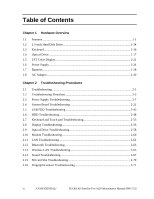 6
6 -
 7
7 -
8
-
9
-
10
-
11
-
12
-
13
-
14
-
15
-
16
-
17
-
18
-
19
-
20
-
21
-
22
-
23
-
24
-
25
-
26
-
27
-
28
-
29
-
30
-
31
-
32
-
33
-
34
-
35
-
36
-
37
-
38
-
39
-
40
-
41
-
42
-
43
-
44
-
45
-
46
-
47
-
48
-
49
-
50
-
51
-
52
-
53
-
54
-
55
-
56
-
57
-
58
-
59
-
60
-
61
-
62
-
63
-
64
-
65
-
66
-
67
-
68
-
69
-
70
-
71
-
72
-
73
-
74
-
75
-
76
-
77
-
78
-
79
-
80
-
81
-
82
-
83
-
84
-
85
-
86
-
87
-
88
-
89
-
90
-
91
-
92
-
93
-
94
-
95
-
96
-
97
-
98
-
99
-
100
-
101
-
102
-
103
-
104
-
105
-
106
-
107
-
108
-
109
-
110
-
111
-
112
-
113
-
114
-
115
-
116
-
117
-
118
-
119
-
120
-
121
-
122
-
123
-
124
-
125
-
126
-
127
-
128
-
129
-
130
-
131
-
132
-
133
-
134
-
135
-
136
-
137
-
138
-
139
-
140
-
141
-
142
-
143
-
144
-
145
-
146
-
147
-
148
-
149
-
150
-
151
-
152
-
153
-
154
-
155
-
156
-
157
-
158
-
159
-
160
-
161
-
162
-
163
-
164
-
165
-
166
-
167
-
168
-
169
-
170
-
171
-
172
-
173
-
174
-
175
-
176
-
177
-
178
-
179
-
180
-
181
-
182
-
183
-
184
-
185
-
186
-
187
-
188
-
189
-
190
-
191
-
192
-
193
-
194
-
195
-
196
-
197
-
198
-
199
-
200
-
201
-
202
-
203
-
204
-
205
-
206
-
207
-
208
-
209
-
210
-
211
-
212
-
213
-
214
-
215
-
216
-
217
-
218
-
219
-
220
-
221
-
222
-
223
-
224
-
225
-
226
-
227
-
228
-
229
-
230
-
231
-
232
-
233
-
234
-
235
-
236
-
237
-
238
-
239
-
240
-
241
-
242
-
243
-
244
-
245
-
246
-
247
-
248
-
249
-
250
-
251
-
252
-
253
-
254
-
255
-
256
-
257
-
258
-
259
-
260
-
261
-
262
-
263
-
264
-
265
-
266
-
267
-
268
-
269
-
270
-
271
-
272
-
273
-
274
-
275
-
276
-
277
-
278
-
279
-
280
-
281
-
282
-
283
-
284
-
285
-
286
-
287
-
288
-
289
-
290
-
291
-
292
-
293
-
294
-
295
-
296
-
297
-
298
-
299
-
300
-
301
-
302
-
303
-
304
-
305
-
306
-
307
-
308
-
309
-
310
-
311
-
312
-
313
-
314
-
315
-
316
-
317
-
318
-
319
-
320
-
321
-
322
-
323
-
324
-
325
-
326
-
327
-
328
-
329
-
330
-
331
-
332
-
333
-
334
-
335
-
336
-
337
-
338
-
339
-
340
-
341
-
342
-
343
-
344
-
345
-
346
-
347
-
348
-
349
-
350
-
351
-
352
-
353
-
354
-
355
-
356
-
357
-
358
-
359
-
360
-
361
-
362
-
363
-
364
-
365
-
366
-
367
-
368
-
369
-
370
-
371
-
372
-
373
-
374
-
375
-
376
-
377
-
378
-
379
-
380
-
381
-
382
-
383
-
384
-
385
-
386
-
387
-
388
-
389
-
390
-
391
-
392
-
393
-
394
-
395
-
396
-
397
-
398
-
399
-
400
-
401
-
402
-
403
-
404
-
405
-
406
-
407
-
408
-
409
-
410
-
411
-
412
-
413
-
414
-
415
-
416
-
417
-
418
-
419
-
420
-
421
-
422
-
423
-
424
-
425
-
426
-
427
-
428
 |
 |

[CONFIDENTIAL]
Toshiba Personal Computer
TECRA A8 series /
Satellite Pro A120 series
Maintenance Manual
TOSHIBA CORPORATION
File Number 960-573