Viking VIPR161SS Installation Instructions - Page 5
Plan The Wiring, Prepare The Downdraft - replace motor
 |
View all Viking VIPR161SS manuals
Add to My Manuals
Save this manual to your list of manuals |
Page 5 highlights
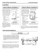
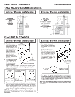
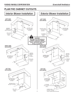
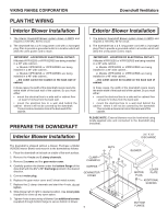
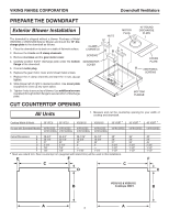
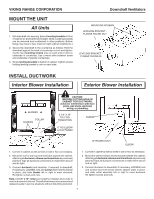
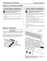
VIKING RANGE CORPORATION Downdraft Ventilators PLAN THE WIRING Interior Blower Installation 1. The Interior Downdraft Blower system draws 4 AMPS and requires a 120 VAC, 60 Hz circuit. 2. The downdraft has a 2 ft. long power cord with a 3-pronged plug. Plan to provide a grounded outlet in a location which will allow the unit's power cord to reach. IMPORTANT - LOCATION OF ELECTRICAL OUTLET: If Models VIPR102SS or VIPR102RSS are being installed in a 30" wide cabinet... or Models VIPR162SS or VIPR162RSS are being installed in a 36" wide cabinet... or Models VIPR182SS or VIPR182RSS are being installed in a 48" wide cabinet... ...the outlet cannot be located on the back wall of cabinet. In these cases, the width of the downdraft covers nearly the entire width of the back wall of the cabinet. So you must either: • mount the electrical box to a side wall or cabinet floor - at least 12 inches from the back wall. • mount the electrical box to a wall stud behind the cabinet - where it will not be covered by the downdraft. Then provide a clearance hole in the back wall of the cabinet. PREPARE THE DOWNDRAFT Interior Blower Installation Exterior Blower Installation 1. The Exterior Downdraft Blower system draws 6 AMPS and requires a 120 VAC, 60 Hz circuit. 2. The downdraft has a 2 ft. long power cord with a 3-pronged plug. Plan to provide a grounded outlet in a location which will allow the unit's power cord to reach. IMPORTANT - LOCATION OF ELECTRICAL OUTLET: If Models VIPR102SS or VIPR102RSS are being installed in a 30" wide cabinet... or Models VIPR162SS or VIPR162RSS are being installed in a 36" wide cabinet... or Models VIPR182SS or VIPR182RSS are being installed in a 48" wide cabinet... ...the outlet cannot be located on the back wall of cabinet. In these cases, the width of the downdraft covers nearly the entire width of the back wall of the cabinet. So you must either: • mount the electrical box to a side wall or cabinet floor - at least 12 inches from the back wall. • mount the electrical box to a wall stud behind the cabinet - where it will not be covered by the downdraft. Then provide a clearance hole in the back wall of the cabinet. PLEASE NOTE: External blowers must be hard-wired using locally-supplied wire and connected to the downdraft plug (included). 3¼" X 10" DISCHARGE The downdraft is shipped without a blower. Purchase a Model VIDV500 Interior Blower and mount it to the downdraft as follows: 1. Place the downdraft on its back on a table of flat work surface. 2. Remove the 4 nuts and 2 clamp channels. 3. Remove 2 screws and the gear motor cover. 4. Carefully position the blower under the bottom flange of the downdraft with the 3¼" x 10" discharge pointed in the desired direction. 5. Connect motor plug. 6. Replace the gear motor cover and 2 sheet metal screws. 7. Replace the 2 clamp channels and start the 4 nuts, do not tighten. 8. Slide blower left of right to desired position. Use cover plate (supplied) to close up any open space. 9. Tighten 4 nuts to secure top of blower. Use additional screws (supplied) through bottom flange to secure bottom in blower. CLAMP CHANNELS SCREWS GEARMOTOR COVER 5 NUTS BLOWER MOTOR PLUG COVER PLATE ADDITIONAL SCREWS BOTTOM FLANGE
-
 1
1 -
 2
2 -
 3
3 -
 4
4 -
 5
5 -
 6
6 -
 7
7 -
 8
8 -
 9
9 -
 10
10 -
 11
11 -
12
-
13
-
14
-
15
-
16
-
17
-
18
-
19
-
20
-
21
-
22
-
23
-
24
-
25
-
26
-
27
-
28
-
29
-
30
-
31
-
32
-
33
-
34
-
35
-
36
 |
 |