Weider Pro 9450 Uk Manual
Weider Pro 9450 Manual
 |
View all Weider Pro 9450 manuals
Add to My Manuals
Save this manual to your list of manuals |
Weider Pro 9450 manual content summary:
- Weider Pro 9450 | Uk Manual - Page 1
if there are missing or damaged parts, please call: 08457 089 009 Or write: ICON Health & Fitness, Ltd. Unit 4 Revie Road Industrial Estate Revie Road Beeston Leeds, LS11 8JG UK email: [email protected] CAUTION Read all precautions and instructions in this manual before using this equipment. Save - Weider Pro 9450 | Uk Manual - Page 2
BEGIN 4 ASSEMBLY 5 ADJUSTMENTS 21 WEIGHT RESISTANCE CHART 23 TROUBLESHOOTING AND MAINTENANCE 24 CABLE DIAGRAMS 25 ORDERING REPLACEMENT PARTS Back Cover Note: A PART IDENTIFICATION CHART and a PART LIST/EXPLODED DRAWING are attached at the centre of this manual. Remove the PART IDENTIFICATION - Weider Pro 9450 | Uk Manual - Page 3
The weight system is designed to support a a maximum user weight of 115 kg (250 lbs.). 9. Keep hands and feet away from moving parts. 10. Always disconnect the lat age of 35 or persons with pre-existing health problems. Read all instructions before using. ICON assumes no responsibility for personal - Weider Pro 9450 | Uk Manual - Page 4
or improve your cardiovascular system, the PRO 9450 weight system will help you to achieve the specific results you want. For your benefit, read this manual carefully before using the weight system. If you have additional questions, please call our Customer Service Department toll-free at 08457 089 - Weider Pro 9450 | Uk Manual - Page 5
as shown in the drawings. • Tighten all parts as you assemble them, unless instructed to do otherwise. • For help identifying the small parts used in assembly, use the PART IDENTIFICATION CHART located in the centre of this manual. Note: Some small parts may have been preattached for shipping. If - Weider Pro 9450 | Uk Manual - Page 6
2. Slide the Rear Upright (74) and the Leg Press Upright (56) onto the indicated 5/16" x 2 1/2" Carriage Bolts (1) in the Stabiliser (5). The high side of the brackets on the Rear Upright and Leg Press Upright should be on the side shown. Hand tighten four 5/16" Nylon Locknuts (3) onto the Carriage - Weider Pro 9450 | Uk Manual - Page 7
4. Press a 2" Square Inner Cap (27) into the end of 4 the Top Frame (55). Press a 1 3/4" Square Inner Cap (44) into each end of the crossbar on the Top Frame. Press two Round Inner Caps (75) into the top of the crossbar. 27 Attach the Top Frame (55) to the Rear Upright (74) and the Leg Press - Weider Pro 9450 | Uk Manual - Page 8
Top Weight (65). Set the Top Weight onto the front stack of Weights (25). Insert both Long Weight Guides (62) into the stack of Weights. Be sure that the holes in the Weight Guides are at the top, as shown. 7 Holes 65 Pin 63 62 Lubricate 64 Pin Grooves 25 8. Press a Weight - Weider Pro 9450 | Uk Manual - Page 9
the upper ends of the Long Weight Guides (62) to the Top Frame (55) with a 5/16" x 6" Bolt (60), two 1/2" x 3/4" Spacers (61), and a 5/16" Nylon Locknut (3). 9 61 60 3 61 73 60 3 55 62 ARM ASSEMBLY 10. Locate and open the parts bag labelled "ARM ASSEMBLY." Be sure there is a Bushing (98 - Weider Pro 9450 | Uk Manual - Page 10
with two 5/16" x 2 1/2" Bolts (22) and two 5/16" Nylon Locknuts (3). 22 Assemble the other Press Arm (46) in the same manner. 46 3 17 13. Identify the Right 31 50 Welded Brackets 31 50 47 21 Attach a "V"-Pulley (50) and a Long Cable Trap (31) to the Left Arm (47) in the same manner. 48 14. - Weider Pro 9450 | Uk Manual - Page 11
32 49 32 84 80 67 56 33 80 CABLE ASSEMBLY 16 16. Locate and open the parts bags labelled "CABLE ASSEMBLY" and "PULLEYS." During steps 16 through 36, refer to the CABLE DIAGRAMS on pages 25 and 26 of this manual to verify proper cable routing. Before beginning this section, fully unwind the four - Weider Pro 9450 | Uk Manual - Page 12
68 Locknut (3). Do not over tighten the Nylon Locknut; the Pulley Bracket must be able to move freely. See the inset drawing. Route the High Cable (58) 55 66 around the 3 1/2" Pulley (15) attached to the Pulley Bracket (20). Tighten the 3/8" x 2" Bolt (12) and the 20 12 3/8" Nylon Locknut - Weider Pro 9450 | Uk Manual - Page 13
in a Long "U"-Bracket (57) with a 3/8" x 2" Bolt (12) and a 3/8" Nylon Locknut (21). Note: This may be pre-assembled. Be sure that the small tabs on the Pulley Covers are in the position shown and that the Cable and Pulley move smoothly. 22 Small tabs should be up. 58 77 15 77 21 57 - Weider Pro 9450 | Uk Manual - Page 14
Press Frame (17) with a 3/8" x 3 3/4" Bolt (88), 3/8" Washer (9), and a 3/8" Nylon Locknut (21). Be sure that the parts are oriented as shown in the drawing. Locate the Low Cable (23) and the bag labelled "LOW PULLEY." Route the Low Cable under the 3 1/2" Low Pulley (76). Be sure that the end of the - Weider Pro 9450 | Uk Manual - Page 15
manual. Important: Some parts may have been pre-assembled for shipping purposes. If you cannot find a part in the parts bags, check to see if it has been pre-assembled. Note: The assembly process is divided into four stages: 1) frame assembly, 2) arm assembly, 3) cable assembly, 4) seat assembly - Weider Pro 9450 | Uk Manual - Page 16
PART IDENTIFICATION CHART-Model No. WEEVSY39120 R1202A 3/8" Washer (9) 5/16" Washer (8) 1/4" Washer (10) Selftapping Screw (87) 5/16" Nylon Jam Nut (93) 1/4" x 3/4" Screw (18) 1/4" Nylon Locknut (2) Cable Clip (53) 3/8" x 8" Bolt (59) 1 1/8" x 2 1/2" Plastic Bushing (89) 1" x 7/8" Plastic - Weider Pro 9450 | Uk Manual - Page 17
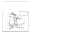
REMOVE THIS PART LIST/EXPLODED DRAWING FROM THE MANUAL. SAVE THIS PART LIST/EXPLODED DRAWING FOR FUTURE REFERENCE Note: Specifications are subject to change without notice. 81 - Weider Pro 9450 | Uk Manual - Page 18
EXPLODED DRAWING-Model No. WEEVSY39120 R1202A 68 86 77 15 77 61 3 27 20 12 27 55 11 8 12 15 75 44 88 15 31 89 50 21 2 12 10 57 78 11 27 60 3 11 10 2 65 105 104 3 99 9 73 87 72 91 71 27 43 10 24 21 88 9 10 2 77 8 15 63 77 3 3 56 37 92 18 77 9 3 85 21 12 - Weider Pro 9450 | Uk Manual - Page 19
1" Round Cover Cap 71 2 Small "U"-Bracket 72 1 Military Press Cable 73 2 Short Weight Guide 74 1 Rear Upright 75 2 Round Inner Cap 76 1 3 1 Ab Strap 104 2 Locking Pin 105 2 Lock * 1 User's Manual * 1 Exercise Guide *These parts are not shown on the EXPLODED DRAWING. - Weider Pro 9450 | Uk Manual - Page 20
- Weider Pro 9450 | Uk Manual - Page 21
1" Round Cover Cap (70) 3/4" Round Inner Cap (34) 5/8" x 9/16" Spacer (7) Round Inner Cap (75) 1" Round Inner Cap (49) 1/2" x 3/4" Spacer (61) 1" Square Inner Cap (6) 1 1/2" Square Inner Cap (32) 2" Square Inner Cap (27) 5/16" x 2" Eyebolt (35) 1 3/4" Square Inner Cap (44) 2" Square Outer - Weider Pro 9450 | Uk Manual - Page 22
Long "U"-Bracket (57) with a 1/4" Nylon Locknut (2) and a 1/4" Washer (10). Do not completely tighten the Nylon Locknut. It should be threaded onto the end of the Cable so only a couple of threads are showing above the Nylon Locknut, as shown in the inset drawing. You may need to lift the Top Weight - Weider Pro 9450 | Uk Manual - Page 23
3/8" Nylon Locknut (21). Make sure the small tabs on the Pulley Covers are on the side shown. See the inset drawing. Wrap the Military Press Cable (72) around another 3 1/2" Pulley (15). Attach the Pulley and a pair of Pulley Covers (77) to the 3/8" x 5 1/4" Bolt (101) on the other side of the Pivot - Weider Pro 9450 | Uk Manual - Page 24
Attach the Press Bracket (94) to the Leg Press Arm 36 (96) with a 3/8" x 3" Bolt (100) and a 3/8" Nylon Jam Nut (99). Wrap the Leg Press Cable (78) around a 3 1/2" Pulley (15). Attach the Pulley and a set of Pulley Covers (77) to the Press Bracket (94) with a 3/8" x 2" Bolt (12) and a 3/8" Nylon - Weider Pro 9450 | Uk Manual - Page 25
37. Locate and open the parts bag labelled "SEAT ASSEMBLY." Insert a 1/4" x 2 1/2" Carriage Bolt (92) through the centre hole in a Seat Plate (37). Attach the Seat Plate to the Leg Press Backrest (85) with two 1/4" x 3/4" Screws ( - Weider Pro 9450 | Uk Manual - Page 26
41. Press a 1 1/2" Square Inner Cap (32) into the Leg 41 Lever (29). Lubricate the 5/16" x 2 1/4" Bolt (33). Attach the Leg Lever (29) to the Front Seat Frame (36) with the Bolt and a 5/16" Nylon Locknut (3). Insert the 3/8" x 2" Eyebolt (35) into the Leg Lever (29) from the direction shown. - Weider Pro 9450 | Uk Manual - Page 27
problem. IMPORTANT: If the cables are not properly installed, they may be damaged when heavy weight is used. See the CABLE DIAGRAMS on page 25 and 26 of this manual for proper cable routing. If there is any slack in the cables, you will need to remove it by tightening the cables. See TROUBLESHOOTING - Weider Pro 9450 | Uk Manual - Page 28
The instructions below describe how each part of the weight system can be adjusted. Refer to the exercise guide accompanying this manual to see to 106.5 pounds, in increments of 12.5 pounds. Note: Due to the cables and pulleys, the amount of resistance 26 at each exercise station may vary from - Weider Pro 9450 | Uk Manual - Page 29
(52) to the Low Cable (23) with a Cable Clip (53). Attach the other end of the Chain to the 3/8" x 2" Eyebolt (35) with a Cable Clip. ADJUSTING THE LEG prevent unauthorised use of the home gym system, insert the Locking Pin (104) into the indicated hole in one of the Weight Guides (62 or 73) and - Weider Pro 9450 | Uk Manual - Page 30
actual resistance at each weight station may vary due to differences in individual weight plates, as well as friction between the cables, pulleys, and weight guides. WEIGHT PLATES PRESS BUTTERFLY ARM ARM (lbs.) (lbs.) LEG LEVER (lbs.) HIGH PULLEY (lbs.) LOW PULLEY (lbs.) MILITARY PRESS ARM - Weider Pro 9450 | Uk Manual - Page 31
cables. The top weight will be lifted off the weight stack. 96 11 8 79 78 93 If a cable tends to slip off the pulleys often, it may have become twisted. Remove the cable and re-install it. 8 93 If the cables need to be replaced, see ORDERING REPLACEMENT PARTS on the back cover of this manual - Weider Pro 9450 | Uk Manual - Page 32
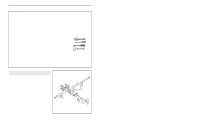
pages show the proper routing of the High Cable (58), the Low Cable (23), the Military Press Cable (72), and the Leg Press Cable (78). Use the diagrams to be sure that the four cables and the cable traps have been assembled correctly. If the cables have not been correctly routed, the weight system - Weider Pro 9450 | Uk Manual - Page 33
Military Press Cable (72) and Leg Press Cable (78) 2 Military Press Cable (72) Rear Weight Stack-1 Ball End 6 8 4 7 1-Long "U"-Bracket 5 3 2 4-Leg Press Seat Frame 3 Leg Press Cable (78) 26 - Weider Pro 9450 | Uk Manual - Page 34
NOTES 27 - Weider Pro 9450 | Uk Manual - Page 35
: • the MODEL NUMBER of the product (WEEVSY39120) • the NAME of the product (WEIDER® PRO 9450 weight system) • the SERIAL NUMBER of the product (see the front cover of this manual) • the KEY NUMBER and DESCRIPTION of the part(s) (see the PART LIST and EXPLODED DRAWING attached at the centre of this
-
 1
1 -
 2
2 -
 3
3 -
 4
4 -
 5
5 -
 6
6 -
 7
7 -
8
-
9
-
10
-
11
-
12
-
13
-
14
-
15
-
16
-
17
-
18
-
19
-
20
-
21
-
22
-
23
-
24
-
25
-
26
-
27
-
28
-
29
-
30
-
31
-
32
-
33
-
34
-
35
 |
 |
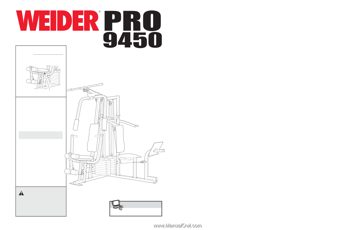
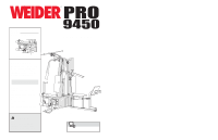
USER'S MANUAL
QUESTIONS?
As a manufacturer, we are com-
mitted to providing complete
customer satisfaction. If you
have questions, or if there are
missing or damaged parts,
please call:
Or write:
ICON Health & Fitness, Ltd.
Unit 4
Revie Road Industrial Estate
Revie Road
Beeston
Leeds, LS11 8JG
UK
email: [email protected]
Model No. WEEVSY39120
Serial No.
Write the serial number in the
space above for reference.
Serial Number Decal (Under Seat)
CAUTION
Read all precautions and
instructions in this manual
before using this equipment.
Save this manual for reference.
www.iconeurope.com
Visit our website at
08457 089 009
Class HC Fitness Product