Weider Pro 9450 Uk Manual - Page 14
Route the Low Cable 23 around a 3 1/2 Pulley
 |
View all Weider Pro 9450 manuals
Add to My Manuals
Save this manual to your list of manuals |
Page 14 highlights
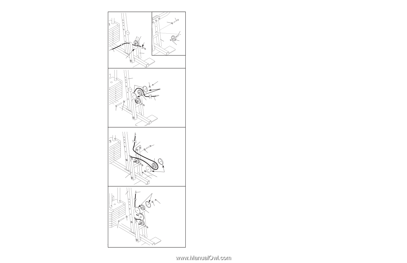
25. Attach the Pulley and the 5/8" x 9/16" Spacer (7) to the Press Frame (17) with a 3/8" x 3 3/4" Bolt (88), 3/8" Washer (9), and a 3/8" Nylon Locknut (21). Be sure that the parts are oriented as shown in the drawing. Locate the Low Cable (23) and the bag labelled "LOW PULLEY." Route the Low Cable under the 3 1/2" Low Pulley (76). Be sure that the end of the Cable with the ball is on the indicated side of the Press Frame, between the Pulley and the crossbar. 25 23 Crossbar 76 Ball 17 88 9 7 17 76 21 26. Route the Low Cable (23) around a 3 1/2" Pulley 26 (15). Attach the Pulley, a set of Pulley Covers (77), and two 3/8" Washers (9) to the lower hole in the Front Upright (42) with a 3/8" Nylon Jam Nut (99) and a 3/8" x 3 3/4" Bolt (88). Be sure the small tabs on the Pulley Covers are in the indicated position. 42 9 99 77 Small tabs should be here. 15 23 88 9 27. Route the Low Cable (23) around a 3 1/2" Pulley (15). Attach the Pulley, a set of Pulley Covers (77), 27 and two 3/8" Washers (9) to the upper hole in the Press Frame (17) with a 3/8" Nylon Locknut (21) and a 3/8" x 3 1/2" Bolt (16). Be sure that the large tabs on the Pulley Covers are in the posi- tion shown. 23 16 9 15 28. Route the Low Cable (23) around another 3 1/2" Pulley (15). Attach the Pulley, a set of Pulley Covers (77), and two 3/8" Washers (9) to the upper hole in the Front Upright (42) with a 3/8" Nylon Jam Nut (99) and a 3/8" x 3 3/4" Bolt (88). Be sure the small tabs on the Pulley Covers are in the indicated position. 17 28 42 9 88 77-Large 21 9 tabs should be here. 23 77-Small tabs should be here. 9 99 15 14
-
 1
1 -
2
-
3
-
4
-
5
-
6
-
7
-
8
-
 9
9 -
 10
10 -
 11
11 -
 12
12 -
 13
13 -
 14
14 -
 15
15 -
 16
16 -
 17
17 -
 18
18 -
 19
19 -
20
-
21
-
22
-
23
-
24
-
25
-
26
-
27
-
28
-
29
-
30
-
31
-
32
-
33
-
34
-
35
 |
 |