Weider Pro 9930 User Manual - Page 14
Cable Trap 39 to the Press Frame Upright 59
 |
View all Weider Pro 9930 manuals
Add to My Manuals
Save this manual to your list of manuals |
Page 14 highlights
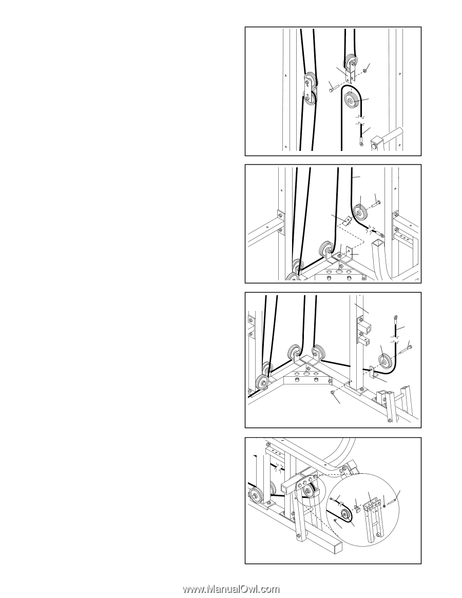
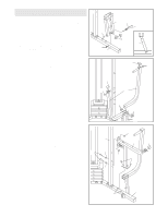
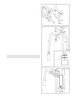
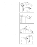
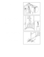
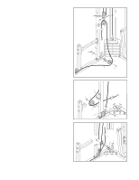
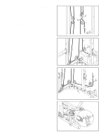
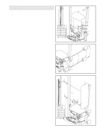
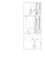
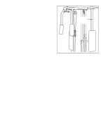
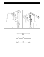
25. Note: For clarity, this and the following drawings 25 show some parts removed. Remove the lower 3 1/2" Pulley (5) from the Double "U"-Bracket (36). Wrap the Long Cable (73) over the Pulley in the direction shown. Attach the Pulley to the Double "U"-Bracket with a 3/8" x 1 3/4" Bolt (22) and a 3/8" Nylon Locknut (4). Make sure that the Double "U"-Bracket is oriented as shown. 26. Wrap the Long Cable (73) around a 3 1/2" Pulley (5) 26 in the direction shown. Attach the Pulley and a Cable Trap (39) to the indicated bracket on the Press Base (60) with a 3/8" x 2" Bolt (35) and a 3/8" Nylon Locknut (4). Make sure that the Cable Trap is oriented as shown. 27. Wrap the Long Cable (73) around the 3 1/2" Pulley 27 (5) in the direction shown. Attach the Pulley and a Cable Trap (39) to the Press Frame Upright (59) with a 3/8" x 4 3/4" Bolt (23). Hand tighten a 3/8" Nylon Locknut (4) two turns onto the Bolt. In step 31, anoth- er Pulley will be attached to the Bolt. 28. Wrap the Long Cable (73) around a 3 1/2" Pulley (5) in the direction shown. Attach the Pulley and a Cable 28 Trap (39) to the indicated hole in the Press Frame (53) with a 3/8" x 3 1/4" Bolt (28), a 3/8" Flat Washer (17), and a 3/8" Nylon Locknut (4). Make sure that the Pulley is mounted on the inside of the Press Frame and that the Cable Trap is oriented as shown. 14 36 4 22 5 73 73 5 35 39 4 60 59 73 5 23 39 4 73 53 39 17 28 45
-
 1
1 -
2
-
3
-
4
-
5
-
6
-
7
-
8
-
 9
9 -
 10
10 -
 11
11 -
 12
12 -
 13
13 -
 14
14 -
 15
15 -
 16
16 -
 17
17 -
 18
18 -
 19
19 -
20
-
21
-
22
-
23
-
24
-
25
-
26
-
27
-
28
-
29
-
30
-
31
 |
 |