Weider Pro 9930 User Manual - Page 9
Arm Assembly
 |
View all Weider Pro 9930 manuals
Add to My Manuals
Save this manual to your list of manuals |
Page 9 highlights
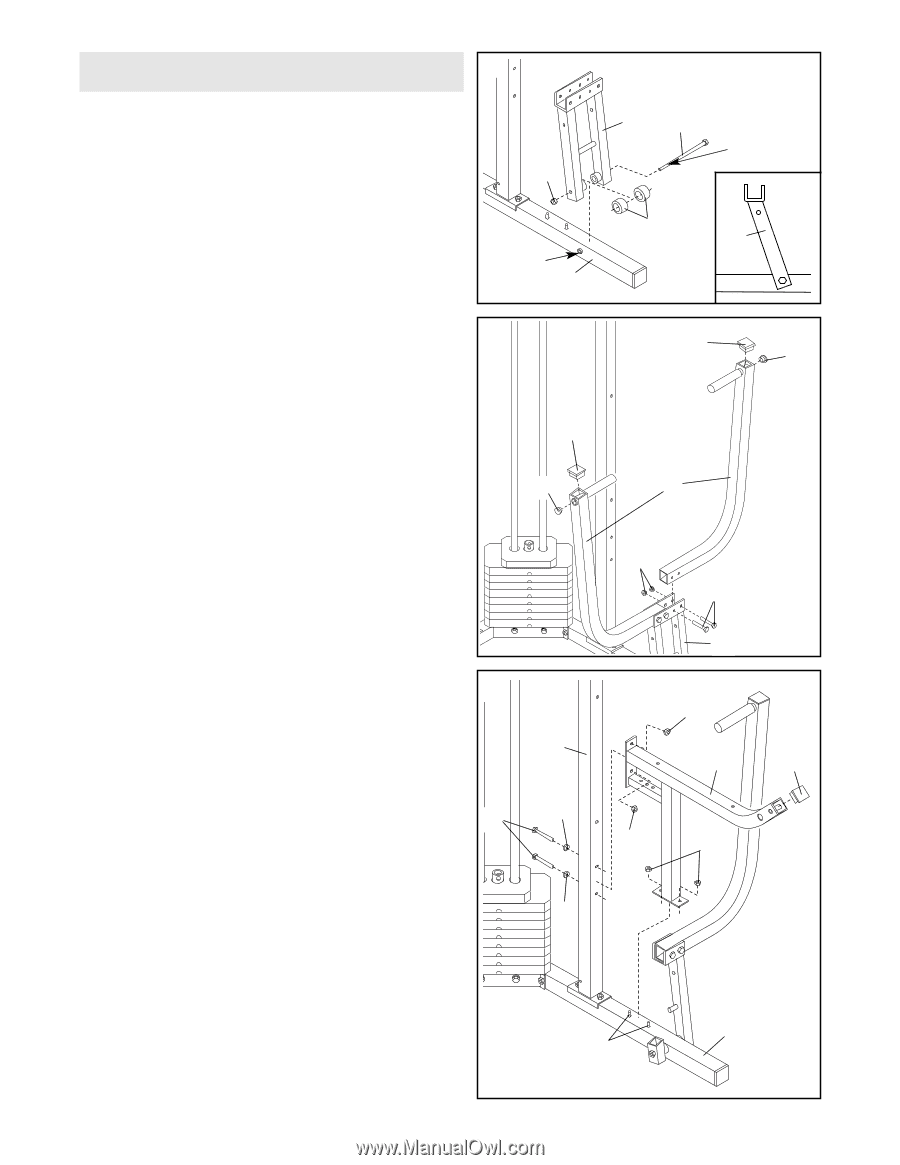
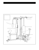
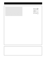
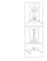
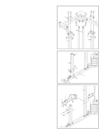
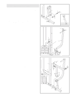
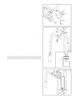
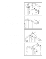
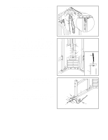
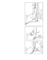
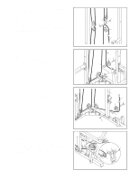
Arm Assembly 9 9. Locate and open the parts bag labelled "ARM ASSEMBLY." Press a 1" x 7/8" Plastic Bushing (29) onto each welded spacer on the Press Frame (53). Slide the Press Frame onto the Press Base (60). (See the inset drawing for proper orientation.) Note: The Plastic Bushings should fit onto the ends of the tube in the Press Base. This will be a tight fit. Lubricate the 3/8" x 8" Bolt (30). Attach the Press Frame (53) to the Press Base (60) with the Bolt and a 3/8" Nylon Locknut (4). Do not overtighten the Nylon Locknut; the Press Frame must pivot easily. 4 Tube 60 10 10. Press a 1 3/4" Square Inner Cap (37) into the top of a Press Arm (54). Press a 1" Inner Cap (80) into the indicated hole in the Press Arm. Attach the Press Arm (54) to the bracket on the Press Frame (53) with two 5/16" x 2 1/2" Bolts (3) and two 5/16" Nylon Locknuts (2). 37 80 Repeat this step to assemble the second Press Arm (54). 11. Press a 1 1/2" Square Inner Cap (79) into the Press Seat Frame (52). 11 Slide the bracket on the lower end of the Press Seat Frame (52) onto the indicated 5/16" x 2 1/2" Carriage 59 Bolts (1) in the Press Base (60). Tighten two 5/16" Nylon Locknuts (2) onto the Bolts. Attach the Press Seat Frame (52) to the Press Frame 20 19 Upright (59) with two 5/16" x 2 3/4" Bolts (20), two 5/16" Flat Washers (19), and two 5/16" Nylon Locknuts (2). 19 53 30 Lubricate 29 53 37 80 54 2 3 53 2 52 79 2 2 60 1 9
-
 1
1 -
2
-
3
-
 4
4 -
 5
5 -
 6
6 -
 7
7 -
 8
8 -
 9
9 -
 10
10 -
 11
11 -
 12
12 -
 13
13 -
 14
14 -
15
-
16
-
17
-
18
-
19
-
20
-
21
-
22
-
23
-
24
-
25
-
26
-
27
-
28
-
29
-
30
-
31
 |
 |