Weslo Gym 1500 Uk Manual - Page 7
Arm Assembly
 |
View all Weslo Gym 1500 manuals
Add to My Manuals
Save this manual to your list of manuals |
Page 7 highlights
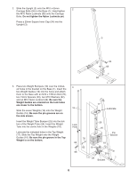
4. Attach the two Base Supports (22) to the Stabiliser (2) with two M10 x 70mm Bolts (64), two M10 Washers (62), and two M10 Nylon Locknuts (68). Attach the Base Supports (22) to the Base (1) with an M10 x 73mm Bolt (80) and an M10 Nylon Locknut (68). Do not tighten the M10 Nylon Locknuts (68) yet. 4 68 68 62 2 64 80 22 22 68 1 64 5. Press two 50mm Square Inner Caps (51) into the ends of the Top Frame (4). Press two 45mm Square Inner Cap (52) into the crossbar on the Top Frame. Attach the Top Frame (4) to the Upright (3) with the Support Plate (86), two M10 x 70mm Bolts (64), and two M10 Nylon Locknuts (68). Attach the Top Frame (4) between the Weight Guides (16) with an M10 x 155mm Bolt (76), two M10 Washers (62), two 19mm Spacers (29), and an M10 Nylon Locknut (68). Tighten the M10 Nylon Locknuts (68) used in steps 1-5. 5 64 51 86 29 76 62 62 29 52 4 51 52 68 68 16 3 Arm Assembly 6. Lubricate both axles on the Top Frame (4) with grease. Identify the Right Butterfly Arm (10) by the position of the bracket. Press a 27mm x 63mm Plastic Bushing (55) into the Right Butterfly Arm, and slide the Arm onto the right axle on the Top Frame. Be sure that the upper end of the Butterfly Arm is behind the indicated bracket on the Top Frame. Tap two 25mm Retainers (50) and a 25mm Cover Cap (49) onto the right axle. Be sure that the teeth on the Retainers bend toward the Cover Cap, as shown in the inset drawing. Attach the Left Butterfly Arm (9) in the same manner. Press two 45mm Square Inner Caps (52) into the lower ends of the Butterfly Arms (9, 10). Wet the end of each Arm with soapy water, and slide two Large Foam Pads (73) onto the Arms. 6 4 Bracket 55 Lubricate Axles 55 50 49 49 10 52 Bracket 9 73 52 Axles 50 73 49 7
-
 1
1 -
 2
2 -
 3
3 -
 4
4 -
 5
5 -
 6
6 -
 7
7 -
 8
8 -
 9
9 -
 10
10 -
 11
11 -
 12
12 -
13
-
14
-
15
-
16
-
17
-
18
-
19
-
20
-
21
-
22
-
23
-
24
-
25
-
26
-
27
 |
 |
