Weslo Gym 1500 Uk Manual - Page 8
Cable Assembly
 |
View all Weslo Gym 1500 manuals
Add to My Manuals
Save this manual to your list of manuals |
Page 8 highlights
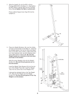
7. Press a 25mm x 22mm Plastic Bushing (81) onto 7 each welded spacer on the Press Frame (6). Slide the Press Frame into place on the Base (1). Note: This will be a tight fit. The Plastic Bushings should fit onto each end of the indi- cated tube in the Base. Be sure that the cage is on the side shown. Lubricate the M10 x 195mm Bolt (75) with grease. Attach the Press Frame (6) to the Base (1) with the Bolt and an M10 Nylon Locknut (68). Do not overtighten the Nylon Locknut; the Press Frame must be able to pivot easily. Press a 45mm Square Inner Cap (52) into the top of a Press Arm (7). Press a 25mm Round Inner Cap (74) into the outer end of the handle on the Press Arm. Slide a Handgrip (31) onto the handle. Attach the Press Arm (7) to one side of the Press Frame (6) with two M8 x 63mm Bolts (69) and two M8 Nylon Locknuts (58). Assemble the other Press Arm (7) in the same manner. 52 74 31 7 58 7 1 68 Tube 6 69 Cage 75 Lubricate Welded Spacer 81 Cable Assembly 8 8. During steps 8 through 19, refer to the CABLE DIAGRAM on page 17 of this manual to verify proper cable routing. Locate the Long Cable (47). Wrap the Long Cable around a 90mm Pulley (44). Attach the Pulley to the Top Frame (4) with an M10 x 90mm Bolt (83), an M10 Washer (62), and an M10 Nylon Locknut (68). Be sure that the Cable is between the Pulley and the hook, and that the end of the Cable with the ball is on the indicated side of the hook. 9 9. Wrap the Long Cable (47) around a "V"-Pulley (45). Attach the Pulley and a Long Cable Trap (46) to the bracket on the side of the Upright (3) with an M10 x 57mm Bolt (59) and an M10 Nylon Locknut (68). Be sure the Cable Trap is turned to hold the Cable in the groove of the Pulley. 4 68 83 62 47 44 Hook 46 45 59 47 68 3 8
-
 1
1 -
2
-
 3
3 -
 4
4 -
 5
5 -
 6
6 -
 7
7 -
 8
8 -
 9
9 -
 10
10 -
 11
11 -
 12
12 -
 13
13 -
14
-
15
-
16
-
17
-
18
-
19
-
20
-
21
-
22
-
23
-
24
-
25
-
26
-
27
 |
 |
