Whirlpool 24-Inch Installation Instructions
Whirlpool 24-Inch - Built-In Dishwasher (Color: Silver) Energy Manual
 |
View all Whirlpool 24-Inch manuals
Add to My Manuals
Save this manual to your list of manuals |
Whirlpool 24-Inch manual content summary:
- Whirlpool 24-Inch | Installation Instructions - Page 1
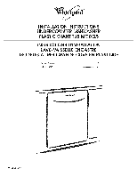
® iNSTALLATiON iNSTRUCTiONS UNDERCOUNTER DISHWASHER PLASTIC GIANT TUB MODELS iNSTRUCTiONS D'INSTALLATION LAVE-VAISSELLE ENCASTRE MODELES A TRESGRANDE CUVE EN PLASTIQUE Table of Contents 2 Table des mati_res 21 W10282553A - Whirlpool 24-Inch | Installation Instructions - Page 2
the rear of the dishwasher. Remove shipping materials, drain hose and lower rack. Close dishwasher door until latched. • Observe all governing codes and ordinances. • Install this dishwasher as specified in these instructions. • Installation should be performed by a qualified service technician. The - Whirlpool 24-Inch | Installation Instructions - Page 3
needed: Compr x _ Hose Fatting FOr part or kit, see local retailer or call Whirlpool Parts: 1-800-442.9991, Part Number w10273460 Other parts drain. • Convenient access for loading and unloading dishes. Corner locations require a 2" (5.1 cm) minimum clearance between the side of the dishwasher door - Whirlpool 24-Inch | Installation Instructions - Page 4
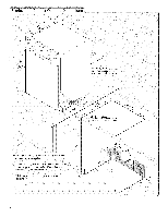
.dels) Check that all surfaces have no protrusions that would prohibit dishwasher installation. NOTSEh: adaerdeoafcabinwetallshowheruetility connectimonasybeinstalled. *MeasufrreodmthelowesptoinotntheundersOidfe countertMopa.ybereducteod33_(86cmb) y removiwnhgeeflrsomdishwasher. "_Minimmumea - Whirlpool 24-Inch | Installation Instructions - Page 5
by a licensed plumber. 120°F (49°C) water at dishwasher. 3/8" O.D. copper tubing with compression fitting or flexible braided water supply line (Part Number 4396897RP) NOTE: 1/2" minimum plastic tubing is not recommended. A 90 ° elbow with 3/8" NET. external pipe threads on one end. Do not solder - Whirlpool 24-Inch | Installation Instructions - Page 6
shown, proceed to the "install Drain Hose" section. If they do not reach far enough, follow the instructions in the "Prepare Cabinet Opening- Follow Option B instructions Option A, Power Supply Cord: NOTE: A grounded 3 prong outlet is required inside a cabinet next to the dishwasher cabinet opening. - Whirlpool 24-Inch | Installation Instructions - Page 7
front side of cabinet opening). Tape cable to the floor in area shown. This will keep cable from moving when dishwasher a 3/4' (1.9 cm) hole in right-hand cabinet side or rear. See product and cabinet opening dimensions. Drill a 1/2"( 1.3 cm) hole in dishwasher should have a manual shutoff valve. 7 - Whirlpool 24-Inch | Installation Instructions - Page 8
then ferrule, about 1" (2.5 cm) onto copper tubing. NOTE: To avoid vibration during operation, route the water supply line so that it does not touch the dishwasher base, frame or motor. 8 Route drain hose as shown through hole in cabinet to the front center of opening where drain connection will be - Whirlpool 24-Inch | Installation Instructions - Page 9
drain hose connection of the disposer or a waste tee must be made before the drain trap and at least 20" (50.8 cm) above the floor where the dishwasher will black end of drain hose to air gap and cut if needed. NOTE: Do not cut ribbed section. 4. Attach drain hose to air gap with large silver drain - Whirlpool 24-Inch | Installation Instructions - Page 10
fasten the insulation over the molded hooks on the tub. Be sure to fasten the insulation down on both sides of the tub. Helpful Tip: Place cardboard under dishwasher until installed in cabinet opening to avoid damaging floor covering. Do not use door panel as a worktable without first covering with - Whirlpool 24-Inch | Installation Instructions - Page 11
extension cord. Failure to follow these instructions death, fire, or electrical shock. can result in Route cord so that it does not touch dishwasher motor to lower part of dishwasher tub secured. Connect wires black to black and white to white, using UL Listed/CSA Approved twist-on wire connectors. - Whirlpool 24-Inch | Installation Instructions - Page 12
the highest point on the floor). Refer to "Dishwasher Height Adjustment Chart" for wheel position and the number of turns needed. Dishwasher Cabinet opening height 33% (86.0cm) 34 (86,4 cm) Height Adjustment I Wheel position Removed Number of turns on front leg I All the way up ! 1 I. 10 34 - Whirlpool 24-Inch | Installation Instructions - Page 13
Option 2, Dishwasher with Stainless Steel Tub Side Attachment (for marble, granite or other hard surface countertops) 1. Remove the brackets from the parts package. 2. Break off the end of the bracket along the scored line. Built-uflpoors(Kitcheflnoorheighist highethr ancabinet openingE.x) ampKlei: - Whirlpool 24-Inch | Installation Instructions - Page 14
anddrainhoseisneatrhecenteorfthecabineotpening. Ifthedoofrallsopenin, creastheesprintgensiobnymovintghe sprinegndtowartdhebackofthedishwasher. sNidOeTsES. :pringsshoulbdeinthesamenotcheosnleftandright 7J Move dishwasher into ca b in et o p e n in g |: Insulation _ blanket - Whirlpool 24-Inch | Installation Instructions - Page 15
dishwasher "exhead sockeotradjustabwlerench. Be sure rubber washer is properly seated in fitting. repeat previous step. If needed, see website for animated representation of this step. Visit www.whirlpool.com/watersupply FAQ tab. under NOTE: Do not use Teflon _>ttape with compression fittings. - Whirlpool 24-Inch | Installation Instructions - Page 16
, see website for animated representation of this step. Visit www.whirlpool.com/drain under FAQ tab. Make DirectWire Electrical Connection NOTE: If the power supply cord was connected earlier proceed to "Secure Dishwasher in Cabinet Opening" section. Option B, Direct Wire: Using pliers, squeeze - Whirlpool 24-Inch | Installation Instructions - Page 17
ground dishwasher. Connect ground wire to green ground connector in terminal box. Do not use an extension cord. Failure to follow these instructions death, fire, or electrical shock. can result in If needed, see website for animated representation of this step. Visit www.whirlpool.oom - Whirlpool 24-Inch | Installation Instructions - Page 18
NOTED:onotdropscrewisntobottomofdishwasher. Locatberackeotsntopofdishwashaenrdsecurdeishwashtoer countertwopithtwo,#10x1/2P"hillips-hescardew(sincluded). Thedishwashmeursbt esecuretodkeeiptfromshiftinwghen dooirsopened. Chectkhatdishwashisesrtilleveflronto backandsidetoside incabineotpening. - Whirlpool 24-Inch | Installation Instructions - Page 19
Installation Hold the two panels together and place them against dishwasher leg. Using a Phillips or 1A"screwdriver, reinstall the of the lower panel contacts the floor. Adjust if necessary. Check that grounding clip is attached to the lower panel. Position the lower panel behind the access panel - Whirlpool 24-Inch | Installation Instructions - Page 20
and allow it to complete the shortest wash cycle. After the first 2 minutes unlatch door, wait 5 seconds, then open door. Check to see that there is water in the bottom of the dishwasher tub. Check that dishwasher is working properly. if dishwasher is not working properly, disconnect power or - Whirlpool 24-Inch | Installation Instructions - Page 21
d'emplacement 2.2. Dimensions - Produit et cavit6 d'encastrement 23 Sp6cifications de 1'6vacuation 24 Sp6cifications de I'alimentation en eau 24 Sp6cifications 61ectriques 24 Instructions dqnstallation 25 Pr6paration de la cavit6 d'encastrement- Raccordement aux circuits - Whirlpool 24-Inch | Installation Instructions - Page 22
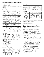
I'installation. Lire et observer les instructions avec chacun des outils de la liste & molette CI6 plate de %" 1% (2.9 cm) . *De taille appropn6e pour le raccordement des pi_ces ou un ensemble, consulter votre marchand local ou Whirlpool Pi_ces : 1-800-442-9991. Num6ro de 22 Pi_ces n6cessaires - Whirlpool 24-Inch | Installation Instructions - Page 23
d'acces pour chargement et d6chargement de la vaisselle; si rappareil est install6 dans un angle, on doit pr6voir un espace libre d'au moins 2" (5,1 cm) entre le c6t6 de la porte du lave-vaisselle et le mur ou le placard adjacent. • bon 6querrage de la cavit6, pour fonctionnement esth6tique - Whirlpool 24-Inch | Installation Instructions - Page 24
tube de plastique ordinaire (dia. min. 1/2"). Un raccord 90 ° avec filetage mSle 3/8" NET. a une extr6mit& Ne pas effectuer une op6ration de soudure a moins de 6" (15,2 cm) de 1'61ectrovanne d'admission d'eau - Whirlpool 24-Inch | Installation Instructions - Page 25
tableau de distribution fusible ou disjoncteur}. Le non=respect de cette instruction peut causer un d_c_s ou un choc _lectrique. Avant d'entreprendie _age du trou Autre ent possible Percer un trou de 1V2" (3,8 cm) dans le panneau lat6ral ou I'arri_re du placard. Voir Dimensions - Produit et - Whirlpool 24-Inch | Installation Instructions - Page 26
) dans le panneau lat@al du placard de droite ou a I'arri@e. Voir Dimensions - Produit et cavit6 d'encastrement. Percer un trou de 1/2"( 1,3 cm) dans le panneau lateral ou I'arriere du placard. Placard en bois : Poncer pour produire une surface lisse dans le trou. Placard metallique : Installer le - Whirlpool 24-Inch | Installation Instructions - Page 27
le plus proche de 1'6vier. Canalisation en cuivre uniquement " Enfiler I'ecrou puis la virole sur la canalisation de cuivre, sur environ 1" (2,5 cm). REMARQUE : Pour reduire les vibrations durant le fonctionnement, acheminer la canalisation d'alimentation en eau de telle maniere qu'elle ne touche - Whirlpool 24-Inch | Installation Instructions - Page 28
circuit de plomberie en amont du pi_ge/siphon, et a 20" (50,8 cm) ou plus au-dessus du plancher de la cavit6 d'encastrement. T du Conseil d'6vacuation a 6t6 coup6, utiliser une bride vis de 11W'_ 2" (3,8 _ 5 cm)(pas fournie). 5. Installer un tuyau de caoutchouc (pas fourni) entre le brise-vide - Whirlpool 24-Inch | Installation Instructions - Page 29
pas utiliser le lave=vaisselle cornpl_ternent install6. jusqu'a Ne pas appuyer sur la porte ouverte. ce qu'il soit Le non=respect de ces instructions blessures graves ou des coupures. peut causer des Risque du poids excessif Utiliser deux personnes ou plus pour d_placer et installer le lave - Whirlpool 24-Inch | Installation Instructions - Page 30
sera utiiise? Cordon d alimentati0n : i Voir les instructions pour I Option A ! C_b!age direct: Voir! la borne. vert reli_ Ne pas utiliser un c_ble de rallonge. Le non=respect de ces instructions peut causer un d_c_s, un incendie ou un choc _lectrique. Connecteur de liaison Oter la vis - Whirlpool 24-Inch | Installation Instructions - Page 31
sultleersiteInternewtww.whirlpool.comongleFt andt'enavoirre,cu I'instruction. Dimensions de la cavif d'espace; ceci permettra I'installation du lave-vaisselle dans une ouverture de 337/8" (86 cm), mais il sera alors difficile de d6placer le lave-vaisselle (les dimensions sont approximatives). Les - Whirlpool 24-Inch | Installation Instructions - Page 32
I'illustration pour 6tablir la distance de 34" (86,4 cm) entre la surface des cales et le plan de lave=vaisselle. Le non=respect de cette instruction peut causer une blessure au dos ou d' au placard. On trouvera deux supports dans le sachet de pieces. Fixer les supports au sommet du lave-vaisselle - Whirlpool 24-Inch | Installation Instructions - Page 33
Faire intervenir deux personnes ou plus pour redresser le lavevaisselle. REMARQUE : Ne pas installer le panneau de plinthe avant d'en avoir recu I'instruction. proximite i i ii i:i de I'ouverture "/ ' Canalisatior d'eau Tandis qu'une autre personne maintient le lave-vaisselle pour qu'il ne puisse - Whirlpool 24-Inch | Installation Instructions - Page 34
Silaportesefermetroprapidemern6td, uirleatensiodnes rveesrssI'oarv:tdasendptullaacveleer-pvoaiinsdts'ealnlec.ragdeI'extr6mdit6uressort REMARQ:UUEtiliseler m_mpeoindt 'ancrag(eencochpeo)ur chaqureesso(rct 6t6gaucheetc6t6droit). Augmentation de la tension du ressorl 6-_La porte s'ouvre et retombe - - Whirlpool 24-Inch | Installation Instructions - Page 35
. Si une fuite se produit, r_p_ter I'_tape precedente. Au besoin, visiter le site Web pour une representation cette _tape. Visiter w_v.whirlpool.com/watersupply I'onglet FAQ. video de sous REMARQUE : Ne pas utiliser du ruban de Teflon - Whirlpool 24-Inch | Installation Instructions - Page 36
. Lorsquleraccordemeesnttermin6e,nlevelarserviette. Le non-respect de ces instructions peut causer un d_c_s, un incendie ou un choc _lectrique. Sin6cessaciroen, sultleersiteInternet v_ww.whirlpool.com/(dornaginleFtAQq)uipr6senutene descriptivoind6odecette6tape. 2J CSbiage direct- Raccordement - Whirlpool 24-Inch | Installation Instructions - Page 37
conducteur de Si n6cessaire, consulter le site Internet w_Jv.whirlpool.com/electrical (onglet FAQ) qui 3resente une description vid60 doit utiliser I'ensemble de montage lat6ral (piece no 8212560). Ex6cuter les instructions pour installer les brides fournies avec I'ensemble. Placer les fils a - Whirlpool 24-Inch | Installation Instructions - Page 38
. Retirelarserviettdeeprotectioqnuai vai6t t6plac6aeufonddu lave-vaisseRl6lein. stallleepranieinr f6rieur. Sin6cessaciroen, sultleersiteInternet www.whirlpool.com/anch(orninggleFtAQq)uipr6senutene descriptiovind6odecette6tape. iiiii i _iiiiiiiiii_i_i/i/i/i/_ Achever I'installation - Whirlpool 24-Inch | Installation Instructions - Page 39
a la terre. hie pas utiliser un adaptateur. hie pas utiliser un c_ble de rallonge. Le non=respect de ces instructions peut causer un d_c_s, un incendie ou un choc _lectrique. Verifierquelariveinferieurdeupanneaiunferieuer stau contacdt uplancheLr.ereajustearubesoin. Serrer les vis du panneau - Whirlpool 24-Inch | Installation Instructions - Page 40
eviter le coot d'une intervention de service, essayer d'abord les suggestions de solution de basse puissance, a faible consommation d'energie, ex6cute des programmes de plus Iongue dur6e Whirlpool Corporation. All rights reserved. ® Registered Trademark/TM Trademark of Whirlpool, U.S.A., Whirlpool
-
 1
1 -
 2
2 -
 3
3 -
 4
4 -
 5
5 -
 6
6 -
 7
7 -
8
-
9
-
10
-
11
-
12
-
13
-
14
-
15
-
16
-
17
-
18
-
19
-
20
-
21
-
22
-
23
-
24
-
25
-
26
-
27
-
28
-
29
-
30
-
31
-
32
-
33
-
34
-
35
-
36
-
37
-
38
-
39
-
40
 |
 |
®
iNSTALLATiON iNSTRUCTiONS
UNDERCOUNTER DISHWASHER
PLASTIC GIANT
TUB
MODELS
iNSTRUCTiONS D'INSTALLATION
LAVE-VAISSELLEENCASTRE
MODELES A TRESGRANDE CUVE EN PLASTIQUE
Table
of Contents
................................................
2
Table
des mati_res
..............................................
21
W10282553A