Whirlpool WOES5030LB Owners Manual - Page 20
Install Deflector Kit (on some models), Parts Supplied in Deflector Kit, Install Deflector Kit
 |
View all Whirlpool WOES5030LB manuals
Add to My Manuals
Save this manual to your list of manuals |
Page 20 highlights
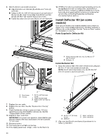
6. After the bottom vent shield is installed. � Align the bottom vent trim tab (B) with the oven frame (A) as shown. � Using one #8-18 x 3/8" (9.5 mm) screw (C) on each side of the trim tab (B), align the top edge of the bottom vent trim tab (E) with the hinge receiver edge (D) as shown. � Fasten the bottom vent trim securely to the oven frame (A). A 14. If F9E0 error code is encountered upon powering up the unit, the appliance is wired incorrectly at the Junction Box or Electrical Panel. Contact a qualified electrician to verify the home electrical supply and the hardwire connection at the Junction Box or Electrical Panel (See the Electrical Connection Options section). Install Deflector Kit (on some models) On single and double oven models installed above a warming drawer or for ovens installed using flush installation cabinetry, a deflector kit must be installed. See the "Tools and Parts" section for information on ordering. Parts Supplied in Deflector Kit A B B C A. Phillips head screws (4), only 2 screws for 27" (68.6 cm) size B. Deflector (1) Install Deflector Kit 1. Install the deflector (B) to the lower vent piece (D) using two #8-18 x 1/4" (6.4 mm) screws on each side. NOTE: On 27" (68.6 cm) models, only one #8-18 x 1/4" (6.4 mm) screw is used on each side. A DE B A. Oven frame B. Trim tab C. #8-18 x 3/8" (9.5 mm) screw D. Hinge receiver edge E. Bottom Vent Trim Tab top edge 7. Replace the oven racks. 8. Replace the oven door. See the "Replace Oven Door(s)" section. 9. Check that the door is free to open and close. If it is not, repeat the removal and installation procedures. See the "Prepare Built-In Oven" section. 10. Repeat for lower oven door. IMPORTANT: For proper oven operation, check that the gap between bottom of the door and bottom vent trim is at least 1/4" (6.4 mm). 11. Reconnect power. 12. The display panel will light and boot up. 13. If the display panel does not light, reference the Warranty. B C D A. #8-18 x 1/4" (6.4 mm) screws B. Deflector C. Upper vent piece D. Lower vent piece 2. Align vent tab (B) with oven frame (A) as shown in the following illustration. 20
-
 1
1 -
2
-
3
-
4
-
5
-
6
-
7
-
8
-
9
-
10
-
11
-
12
-
13
-
14
-
 15
15 -
 16
16 -
 17
17 -
 18
18 -
 19
19 -
 20
20 -
 21
21 -
 22
22 -
 23
23 -
 24
24 -
 25
25 -
26
-
27
-
28
-
29
-
30
-
31
-
32
-
33
-
34
-
35
-
36
-
37
-
38
-
39
-
40
-
41
-
42
-
43
-
44
-
45
-
46
-
47
-
48
-
49
-
50
-
51
-
52
-
53
-
54
-
55
-
56
-
57
-
58
-
59
-
60
-
61
-
62
-
63
-
64
-
65
-
66
-
67
-
68
-
69
-
70
-
71
-
72
 |
 |
