Xerox 2135DT Service Guide
Xerox 2135DT - Phaser Color Laser Printer Manual
 |
UPC - 042215474696
View all Xerox 2135DT manuals
Add to My Manuals
Save this manual to your list of manuals |
Xerox 2135DT manual content summary:
- Xerox 2135DT | Service Guide - Page 1
PHASER® 2135 COLOR PRINTER Service Reference Guide Printed on recycled paper 071-0725-00 - Xerox 2135DT | Service Guide - Page 2
PHASER® 2135 COLOR PRINTER Service Quick Reference Guide Warning The following servicing instructions are for use by qualified service personnel only. To avoid personal injury, do not perform any servicing other than that contained in operating instructions unless you are qualified to do so. This - Xerox 2135DT | Service Guide - Page 3
publication may not be reproduced in any form without permission of Xerox Corporation. Phaser®, PhaserShare®, ColorStix®, the TekColor® icon, Made For Each TekColor™ name are trademarks of Xerox Corporation. TekColor CareSM and RealSUPPORTSM are service marks of Xerox Corporation. FTP® Software is a - Xerox 2135DT | Service Guide - Page 4
shock by contacting a qualified service technician to replace fuses inside the product. Do not operate without the covers and panels properly installed. Do not operate in an atmosphere of explosive gases. Safety instructions: Read all installation instructions carefully before you plug the product - Xerox 2135DT | Service Guide - Page 5
earth) terminal: Use caution. Refer to the manual(s) for information: ! WARNING: If the product not wear jewelry: Remove jewelry prior to servicing. Rings, necklaces, and other metallic than 120 or 250 volts AC RMS (depending on printer model) between the supply conductors or between either supply - Xerox 2135DT | Service Guide - Page 6
Phaser 2135 Color Printer 2 Printer RAM and printer capabilities 4 CRC life counter behavior 4 Print engine assemblies 5 The image processor board 8 The control panel 9 On Line LED 9 ! Fault 9 Rear panel 10 Accessing special operating modes 11 System Media-based problems 38 Media problems 38 Multiple - Xerox 2135DT | Service Guide - Page 7
57 Image is not centered on the print 57 The print is wrinkled 57 Macintosh printing problems 58 Image never prints 58 Image is rotated 90 degrees 58 Image prints in black-and-white 58 Printer isn't in the Chooser 59 Windows printing problems 59 Image never prints 59 vi Phaser 2135 Color Printer - Xerox 2135DT | Service Guide - Page 8
color density and balance 77 Printing a Test Page 77 Interpreting the Color Balance test print 77 What to look for 78 Making adjustments 78 Adjustment recovery 79 Cleaning and Maintenance 81 Service Electrical card cage 98 Printer unit chassis 100 Top cover inner frame and front/rear - Xerox 2135DT | Service Guide - Page 9
127 Registration roller assembly B 129 Exit assembly and fuser components 130 Duplex guide assembly 130 Fuser latching handle (front) 132 Fuser latching handle (rear) 134 Fuser exit roller 135 Exit sensor assembly 137 Eject guide assembly 138 Stack full sensor 139 viii Phaser 2135 Color Printer - Xerox 2135DT | Service Guide - Page 10
143 Xerographic components 144 Shutter plate 144 Color registration sensor assembly 145 Color registration solenoid 146 LED assembly 147 Drum contact assembly 148 Toner sensor actuators 149 Duplex unit 151 FRU List 153 Using the parts list 153 Test Prints 173 Wiring Diagram 177 Service Guide ix - Xerox 2135DT | Service Guide - Page 11
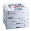
Figures The Phaser 2135 Color Printer with lower tray assembly and lower tray deck 1 Print engine circuit boards 5 Print engine sensor and switch locations 6 Print engine motors, clutches and solenoids 7 Features of the controller board 8 The control panel 9 The printer rear panel 10 Tray switch - Xerox 2135DT | Service Guide - Page 12
145 Removing the color registration solenoid 146 Removing an LED assembly 147 Removing the drum contact assembly 148 Removing the toner sensor actuators 150 Removing the duplex unit 151 Cabinet and top cover FRUs 155 Top cover FRUs 157 Printer chassis FRUs (1 of 2) 159 Printer chassis FRUs (2 of - Xerox 2135DT | Service Guide - Page 13
(2 of 2) 160 FRU of the paper tray and paper tray guides 162 Electrical components FRUs 164 FRUs of the duplexer unit 165 FRUs of the Lower Tray Assembly 166 Hardware kit 168 Gear kit 168 Harness kit 169 Sensor flag kit 170 Customer supplies and accessories 170 xii Phaser 2135 Color Printer - Xerox 2135DT | Service Guide - Page 14
maintaining the Xerox Phaser® 2135 Color Printer. This manual includes troubleshooting guides, adjustment procedures and a field replaceable units (FRU) list. Topics such as printer theory of operation and required service tools are located on the companion Color Printer Service & Support Resources - Xerox 2135DT | Service Guide - Page 15
and capabilities of the Phaser 2135DT printers but includes 256 MBytes of RAM and a three-tray lower tray deck. The printer supports the following resolutions: s 600 x 600 dpi (Normal) s 600 x 1200 dpi (High-quality) The printer also accepts 300 x 300 dpi files from PCL legacy drivers, PCL bit map - Xerox 2135DT | Service Guide - Page 16
runs out of paper. The printer support these tray combination: s One printer's currently defined imaging settings. Auto sensing of PDF files are included in the emulation sensing and switching logic when the PDF option is installed. PDF direct printing requires the internal hard drive. Service Guide - Xerox 2135DT | Service Guide - Page 17
toner, the printer terminates printing at the end of current page and displays the appropriate message on the control panel. No further jobs are accepted from any input port. All printer CRCs wait for the current print job to finish before declaring a Low or Empty state. 4 Phaser 2135 Color Printer - Xerox 2135DT | Service Guide - Page 18
Print engine assemblies Control Panel Board Toner Sensor Board System Controller Board Engine Controller Board Low Voltage Power Supply Board High Voltage Power Supply Board Print engine circuit boards Paper Size Sensor Board Entrance Sensor Board 0725-64 Service Guide 5 - Xerox 2135DT | Service Guide - Page 19
Temperature/ Humidity Sensor Board Belt Entrance Sensor Top Door Open Switch Right-side Door Open Switch Tray 1 Low Paper Sensor Tray 1 Paper Out Sensor Waste Toner Sensor Entrance Sensor Registration Sensor 0725-63 Print engine sensor and switch locations 6 Phaser 2135 Color Printer - Xerox 2135DT | Service Guide - Page 20
Exit Solenoid Registration Motor Registration Clutch Color Registration Shutter Solenoid Tray Lift Motor Cyan Imaging Drum Motor Magenta Imaging Drum Motor Yellow Imaging Drum Motor Black Imaging Drum Motor Print engine motors, clutches and solenoids Paper Feed Motor 0725-62 Service Guide 7 - Xerox 2135DT | Service Guide - Page 21
The image processor board SDRAM ROM DIMM Fan cooled processor Features of the controller board Hard drive 0728-05 8 Phaser 2135 Color Printer - Xerox 2135DT | Service Guide - Page 22
consists of eight labeled keys. These keys navigate the menu system for printer operations. Two LEDs on the display indicate On Line and of once per second. ! Fault Red in color, this LED illuminates whenever operator intervention is required, such as a paper jam in the printer. Service Guide 9 - Xerox 2135DT | Service Guide - Page 23
printer rear panel The LED LNK is off when the printer is not installed on an Ethernet network, it blinks while data is transmitted to the host. The LED SPD is off when the card is set for 4 megabits-per-second (MBPS), on when the card is set for 16 MBPS. 10 Phaser 2135 Color Printer - Xerox 2135DT | Service Guide - Page 24
Down (5) To exit, switch the printer power off, then on. This system controller board. The LED HDD, illuminates to flashes to indicate hard drive read/write activity. LED GIO2 flashes to indicate proper CPU operation. LED GIO3; off indicates 10baseT connection, on indicates 100baseT. Service Guide - Xerox 2135DT | Service Guide - Page 25
the paper tray, is set according to the position of the tray's paper guides. Upon insertion of the tray in the printer, the plate's four rows of slots activate four switches. The combinations of sensor board Back of paper tray Tray switch sensors and actuators 12 Phaser 2135 Color Printer 0725-67 - Xerox 2135DT | Service Guide - Page 26
lbs.) Each additional lower tray adds 16.8 kgs (37 lbs.). The lower tray deck weights 57.7 kbs (127 lbs) Printer clearances Clearances Top: Left: Right: Front: Rear: Mounting surface flatness: Specification 91.5 cm (36 in.) 30.5 all four feet in contact with the table surface. Service Guide 13 - Xerox 2135DT | Service Guide - Page 27
bond laser printer or copier paper, Xerox-brand Phaser 35-series A- and A4-size transparency film is supported. Automatic two-sided printing: 75 to 120 g/m2 (20 to 32 lb.) A6 paper, transparency film, heavy card stock, and glossy paper are not supported by Trays 2 thru 5 14 Phaser 2135 Color Printer - Xerox 2135DT | Service Guide - Page 28
F) 0 too 32 Co (32 to 90 Fo) -10 to 43 C (-14 to 109 F) (with supplies) Media should be acclimated 24 hours before using in the printer. 10 to 80% relative humidity, non-condensing 10 to 90% relative humidity, non-condensing Media should be acclimated 24 hours before using in the - Xerox 2135DT | Service Guide - Page 29
. Standby: 45 dBa, Running: 54 dBa, Impulse: 57 dBa Regulatory specifications The printer is a recognized component in conformance with the following regulatory standards: s The packaged product meets VAC equipment) pursuant to Sub-part J of Part 15. ICES 03 Class B 16 Phaser 2135 Color Printer - Xerox 2135DT | Service Guide - Page 30
system failures. These error codes are discussed in the next topic. Except for media jams and other such errors, when an error code first occurs, cycle power on the printer to see if the error re-occurs. Printer fault messages Code A6 A7 A10 Front panel message Service of the printer, inspect the - Xerox 2135DT | Service Guide - Page 31
Printer fault messages Code A11 A22 B8 B13 Front panel message Service message Jam Inside Top Cover, Open Cover, See Labels A11-Paper Feed Jam 1. Ensure the Motor and clutch tests" on page 69. 5. Replace the duplex unit. 6. Replace the engine controller board. 18 Phaser 2135 Color Printer - Xerox 2135DT | Service Guide - Page 32
Printer fault messages Code B21 C1 C2 C3 C4 C5 E1 E2 E3 E4 E5 E9 E12 Front panel message Service message Jam Inside Right Door A, Open Right Door A B21-Duplex Area Jam 1. Ensure the page 63. 3. Inspect the sensor and its wiring harness. 4. Replace the engine controller board. Service Guide 19 - Xerox 2135DT | Service Guide - Page 33
1. Remove and install the drum unit. 2. Inspect the spring-loaded drum contact assembly. Ensure they are clean and move up and down freely. Remove the assembly and reseat it, if necessary. 3. Replace the engine controller board. 4. Replace the printer unit chassis 20 Phaser 2135 Color Printer - Xerox 2135DT | Service Guide - Page 34
Printer fault messages Code EE EF H1 H2 H3 J3 J4 Front panel message Service message Transfer the submenu item Disk Init. 4. Replace the hard drive. 5. Replace the system controller board. Replace Fuser J3-Replace Fuser 1. Install a new fuser. 2. engine controller board. Service Guide 21 - Xerox 2135DT | Service Guide - Page 35
paper size sensors and the tray's corresponding sensor flags. 4. Replace the paper tray sensor board. 5. Replace the paper tray. 6. Replace the engine controller board. 22 Phaser 2135 Color Printer - Xerox 2135DT | Service Guide - Page 36
Printer fault messages Code T1 T2 T29 T30 T31 T32 Front panel message Service message Fuser Upper Error T1 Power is operating and is not blocked. 2. Ensure the printer is operating in the correct temperature environment; the printer's Service Menu : Print Diag Summary test page lists the ambient - Xerox 2135DT | Service Guide - Page 37
Printer fault messages Code U0 U1 U2 U3 U4 U5 U6 U7 U8 U9 U10 Front panel message Service Feeder Home Error U7, Power Off/On U7-Feeder Home Error 1. Test the manual bypass feeder home sensor using the test described in "Switch scan test" on page controller board. 24 Phaser 2135 Color Printer - Xerox 2135DT | Service Guide - Page 38
connector faces rearward). Inspect the printer's corresponding connector on the printer chassis (covered by a flexible toner sensor boards wiring harness. 4. Replace the toner sensor board. 5. Replace the engine control board. Yellow Drum Error U26, Power Off/On U26-Yellow Drum Error Service Guide - Xerox 2135DT | Service Guide - Page 39
" messages will not go away. 1. Remove the CRC. 2. Cycle the printer's power. 3. Install the CRC again. If the error still occurs, try a different CRC. 4. If error reoccurs with a different CRC, replace the engine controller board. 5. Replace the print unit chassis. 26 Phaser 2135 Color Printer - Xerox 2135DT | Service Guide - Page 40
board Bad system controller board Bad system controller board Bad system controller board Bad system controller board Bad system controller board Bad system controller board Bad hard disk drive Bad hard disk drive Bad hard disk drive Bad hard disk drive Bad hard disk drive Service Guide 27 - Xerox 2135DT | Service Guide - Page 41
. Replace the hard drive before replacing the controller board. Video Task Serial Task System Display Task System Status Task Startup, Key Press Processing, Menus Task Parallel Port Read Buffer Manager Parallel Manager Image Handler Job Manager PowerSaver Task TIFF Task 28 Phaser 2135 Color Printer - Xerox 2135DT | Service Guide - Page 42
This topic discusses troubleshooting the printer. Troubleshooting is discussed with two approaches: s A step-by-step verification procedure that systematically confirms that particular components of the printer are properly functioning until a problem is found. s A symptom/cause scheme that - Xerox 2135DT | Service Guide - Page 43
drums printer. s The print engine checks the presence of each toner printer is placed on line in its READY state. The print engine is initialized. If the startup page feature has not been disabled and no error occurred with the printer, the printer prints a startup page. 30 Phaser 2135 Color Printer - Xerox 2135DT | Service Guide - Page 44
working correctly. Proceed with the next topic, "Verifying printer operation by using its self-test print" on page 32. If the printer does not make the test print, then a problem exists with the print engine. Proceed with the topic, "Verifying power supply operation" on page 32. Service Guide 31 - Xerox 2135DT | Service Guide - Page 45
voltages 1. Turn off the printer and unplug it from its power outlet. 2. AC Input: With the DMM set to measure AC voltages, measure for power being supplied to the printer. It should measure between 87 to 128 VAC (115 VAC nominal) or 174 to 250 VAC (220 VAC nominal). 32 Phaser 2135 Color Printer - Xerox 2135DT | Service Guide - Page 46
, proceed to the next step, "Inspecting the low-voltage power supply fuse" on page 34. If the +5 and +32 VDC voltages measure correctly, but the printer does not operate correctly, then proceed to the topic, "Safety interlocks" on page 34. Service Guide 33 - Xerox 2135DT | Service Guide - Page 47
, the +32 VDC supply to the duplex unit and high-voltage power supply is disabled. 1. Turn off the printer. 2. With a DMM set to measure resistance, test each switch when it is opened and closed. 3. Inspect appear to be at fault, replace the engine controller board. 34 Phaser 2135 Color Printer - Xerox 2135DT | Service Guide - Page 48
cable OPTN to the toner sensor board. The +5V is then routed back out the toner sensor board through its bump" or the engine board LED (LED2) flash. To troubleshoot the loop: 1. Test surface-mount fuse F6 for continuity. It harness leading form the toner sensor board to the power supply features an - Xerox 2135DT | Service Guide - Page 49
3. Refer to the topic "Wiring Diagram" on page 215 for a diagram that locates each connector. 4. Turn on the printer again to see if it overloads now that the motors are disconnected from the engine driver board. If the power supply still does not function, replace it. 36 Phaser 2135 Color Printer - Xerox 2135DT | Service Guide - Page 50
the printer). Motor and fuser roller resistances Motor Measure between ... Resistance Yellow drum unit motor Magenta drum unit motor Cyan drum unit motor Black drum unit 2 Ω Open ~360 at 25oC 3 Ω 0 Ω or open (fuse) ~360 at 25oC C D E F C D E F Underside of fuser 0728-02 Service Guide 37 - Xerox 2135DT | Service Guide - Page 51
the printer's condition. 3. Ensure the paper is correctly loaded in the tray. 4. Clean the pick rollers with a clean, dry, lint-free wipe if debris is visible. 5. Replace the paper pick rollers. 6. Check the tray's retard roller for damage. 7. Replace the paper tray. 38 Phaser 2135 Color Printer - Xerox 2135DT | Service Guide - Page 52
printer can handle? 9. Ensure the corners or the paper are under the tabs in the corners of the tray. 10. Replace the paper pick rollers. The paper tray indicates it is empty when it is not The procedure for troubleshooting this problem . 4. Replace the engine controller board. Service Guide 39 - Xerox 2135DT | Service Guide - Page 53
the paper tray for damage to the tray's paper size sensor actuators. 3. Test the printer's paper size sensors using the service test "Switch scan test" on page 63. If the sensors test ok, then the properly? If not, replace it. 10. Replace the engine controller board. 40 Phaser 2135 Color Printer - Xerox 2135DT | Service Guide - Page 54
only Xerox 35-series transparency film meant for this printer. Paper jams at the transfer belt 1. Check for a paper scrap in the paper path. 2. Is the transfer belt assembly correctly installed? 3. Test the transfer belt motor using the service test "Motor and clutch tests" on page 69. Service Guide - Xerox 2135DT | Service Guide - Page 55
the printer. 5. Clean all the eject rollers with a clean, dry, lint-free wipe if debris is visible. 6. Does the exit sensor flag properly actuate its sensor? Test the sensor using the service test "Switch scan test" on page 63. 7. Replace the engine controller board. 42 Phaser 2135 Color Printer - Xerox 2135DT | Service Guide - Page 56
and is not contaminated with toner. Remove an assembly from the printer to inspect, if necessary. 3. Open the top cover, defeat the top cover open switch, and observe if the color imaging drum unit are lifted up and down. 4. Test the drum contact assemblies using service test "Switch scan test" on - Xerox 2135DT | Service Guide - Page 57
AC voltage may be present at Pins 1 and 2 of CN 4-1 and CN 4-2 even though the drivers ICs feeding these pins are damaged and cannot deliver the current required by the fuser heaters. 6. Replace the engine controller board. 7. Replace the low-voltage power supply. 44 Phaser 2135 Color Printer - Xerox 2135DT | Service Guide - Page 58
printer and reseat the system controller board and turn on the printer to determine if seating was the problem. e. Turn off the printer and systematically remove a RAM DIMM and turn on the printer. f. Replace the system controller board. False "No toner low-voltage power supply. Service Guide 45 - Xerox 2135DT | Service Guide - Page 59
Replace the engine controller board Invalid memory DIMM 1. Upon power-up, the system controller board checks each DIMM for information such as data width, clock delay, the printer displays an "Invalid memory DIMM" error message and then continues the boot-up process. 46 Phaser 2135 Color Printer - Xerox 2135DT | Service Guide - Page 60
problems Required tools s #1 Phillips screwdriver s Volt-ohm-meter (VOM) s Conductive grease s Ruler Light or blurred images 1. Is the correct paper being used in the printer? 2. Are the toner cartridges low? 3. Are any of the imaging drum Replace the high-voltage power supply. Service Guide 47 - Xerox 2135DT | Service Guide - Page 61
fans both running? A heat build-up under the imaging units can cause toner to stain the print's background. 5. Do the imaging drum units make good connection to their power terminals? 6. Are the LED heads wiring harnesses. 12. Replace the high voltage power supply. 48 Phaser 2135 Color Printer - Xerox 2135DT | Service Guide - Page 62
Blank print 1. Do the imaging drum units make good connection to their power terminals? 2. Are the LED heads wiring harnesses undamaged and properly seated? 3. the new engine controller board.) 7. Inspect the high-voltage wiring harnesses. 8. Replace the high voltage power supply. Service Guide 49 - Xerox 2135DT | Service Guide - Page 63
path making artifacts parallel to the long axis of the print. Leading Edge 1. Do the imaging drum units make good connection to their power terminals? 2. Are the LED heads wiring harnesses undamaged and wiring harnesses. 8. Replace the high voltage power supply. 50 Phaser 2135 Color Printer - Xerox 2135DT | Service Guide - Page 64
short edge of the print. B-size prints are processed through the printer with the long edge of the print parallel to the paper path with a clean, alcohol-soaked, lint-free wipe. 2. Do the imaging drum units make good connection to their power terminals? 3. Are the LED supply. Service Guide 51 - Xerox 2135DT | Service Guide - Page 65
Poor fusing, toner offsetting 1. Is a supported paper type being used? Try printing on a different brand of paper. 2. Is the fuser unit properly installed used Thick Cardstock Glossy Thin Cardstock Heavy Paper Plain Paper Light Paper Coolest fuser temperature used 52 Phaser 2135 Color Printer - Xerox 2135DT | Service Guide - Page 66
drum unit. s 50 mm (2.0 in.): Developing roller. Replace the imaging drum unit of the affected color. s 44 mm (1.7 in.): Charging roller. Replace the imaging drum unit of the affected color. s 68 mm (2.7 in.): Toner supply roller. Replace the imaging drum unit of the affected color. Service Guide - Xerox 2135DT | Service Guide - Page 67
Ensure the spring-loaded pins travel smoothly up and down. 3. Is a low-toner condition occurring? 4. Replace any imaging drum units you suspect are defective. 5. Are the LED heads' ribbon cables undamaged and harnesses. 11. Replace the high voltage power supply. 54 Phaser 2135 Color Printer - Xerox 2135DT | Service Guide - Page 68
Color misalignments 1. Test the registration sensor as described in the topic "Switch scan test" on page 63. Ensure the registration sensors are clean without toner no toner to fall on the senors. 2. Look for any broken gears in the printer. specifically, inspect the imaging drum gear Service Guide 55 - Xerox 2135DT | Service Guide - Page 69
colors The colors produced by the printer are dramatically different from the color you expected. 1. Look for dirt or contamination on the LED heads. Clean them with a clean, alcohol-soaked, lint-free wipe. 2. If it appears that a single primary color is missing, check that imaging drum's toner - Xerox 2135DT | Service Guide - Page 70
found in the front panel Support Menu / Margin Adjust. 6. printer. Long-grained paper's grain is parallel to the paper path (the direction the paper travels while it is fed through the printer). Rotate A-, A4- and B5-size paper for short-edge feed to see if it makes a difference. Service Guide - Xerox 2135DT | Service Guide - Page 71
driver to ensure that it is version 8.0.x or higher. Earlier versions of the driver do not support color PostScript. 5. The application may require special instructions to print, such as those contained in a PPD file; check in the Phaser 12135 Printer CD-ROM. 58 Phaser 2135 Color Printer - Xerox 2135DT | Service Guide - Page 72
The printer's front panel Receiving data message is displayed as if receiving data, but nothing comes out of printer or the printer goes back to Ready to Print mode without printing an image. 1. From the printer driver, under the printer's set up options, set TRANSMISSION RETRY = 850. Service Guide - Xerox 2135DT | Service Guide - Page 73
- Xerox 2135DT | Service Guide - Page 74
Service Tests and Adjustments Starting the diagnostics mode To start the engine maintenance mode: 1. Turn off the printer. 2. Press and hold the Menu (1) and Enter (4) keys. 3. Turn on the printer maintenance mode to test the printer sensors, test the media transport system, test the imaging LED - Xerox 2135DT | Service Guide - Page 75
. Do not use Table 2 or Table 3. The consumption status of each consumables is displayed in turn. Values show are of prints made and percentage of toner consumed. The life status of the selected consumable is displayed. 62 Phaser 2135 Color Printer - Xerox 2135DT | Service Guide - Page 76
and holding the Menu (1) and Enter (4) keys as you turn on the printer. 2. Press the Menu (1, 5) keys to scroll through the list of test as 1=, 2=, 3=, and 4=) are displayed. 5. With a test active, you can manually actuate the sensors being scanned and look for a change at the control panel. 6. - Xerox 2135DT | Service Guide - Page 77
drum M drum Paper eject sensor Driving roller Y drum Entrance belt sensor K drum not used Black Toner Cartridge Present Cyan Toner Cartridge Present Magenta Toner Cartridge Present transfer unit. Open the top cover and manually rotate the registration roller (use the Phaser 2135 Color Printer - Xerox 2135DT | Service Guide - Page 78
top cover and remove the drum units. Manually rotate the manual bypass feed roller by turning toner dust off the sensor lens and test again. not used not used Encoded fuser roller temperature Temperature is encoded as a hexidecimal value. The default is between 001 and 0D4. not used Service Guide - Xerox 2135DT | Service Guide - Page 79
Place a sheet of paper inside on the sensor flag. Close the cover. Reinsert the duplex unit in the printer. Pull out the duplex unit. Lift its cover. Place a sheet of paper inside on the sensor flag. Tray 2 right-side door and toggle sensor flag below the feed rollers 66 Phaser 2135 Color Printer - Xerox 2135DT | Service Guide - Page 80
not used Open door to test sensor L - Actuated H - Deactuated not used Open the Tray 4 right-side door and toggle sensor flag below the feed rollers Service Guide 67 - Xerox 2135DT | Service Guide - Page 81
temperature L - Installed H - Missing L - Installed H - Missing L - Installed H - Missing L - Installed H - Missing Temperature is encoded as a hexidecimal value. The default is between 083 and 316. Tests the imaging drum up/down sensor. Remove drum unit to test. 68 Phaser 2135 Color Printer - Xerox 2135DT | Service Guide - Page 82
on the upper display. Caution Before running some motor and clutch tests you must remove certain printer consumable items; refer to table below. The front panel also reminds you to remove the necessary 2 to 7 for other motor or clutch tests. 8. Press Enter (4) ends the tests. Service Guide 69 - Xerox 2135DT | Service Guide - Page 83
multi-sheet bypass feeder and observe the paper position plate cycle up and down none Remove the imaging drums and the transfer belt to watch the shutter open and close smoothly and completely. none Open the removed. Observe the pick roller rotate as the motor runs 70 Phaser 2135 Color Printer - Xerox 2135DT | Service Guide - Page 84
Tray 4 and listen for the clutch Remove Tray 5 and listen for the clutch Raises and lowers the imaging drum units Chassis fan, runs for 10 seconds Fuser fan, runs for 10 seconds Run the test with Tray 1 activates the tray 4's lift motor. Watch it raise the l paper lift plate Service Guide 71 - Xerox 2135DT | Service Guide - Page 85
. Lets you select between color or monochrome printing Lets you select between single-sided or double-sided printing. 5. Press the Item (2, 6) keys to scroll to the menu item PRINT EXECUTE. Press Value (3) to starts printing. 6. Press Value (7) to stop printing. 72 Phaser 2135 Color Printer - Xerox 2135DT | Service Guide - Page 86
Celsius) T: Environmental temperature measurement (in degrees Celsius) H: Environmental humidity measurement (in units of%). The key Value (3) changes the display. 7. Press Enter (4) to end the test. Service Guide 73 - Xerox 2135DT | Service Guide - Page 87
counter's count after the replacement of a drum. Initializes the print count after the replacement of a transfer belt unit. Initializes the fuser's print count after the replacement of a fuser unit. Initializes the toner use count after a toner cartridge is replaced 74 Phaser 2135 Color Printer - Xerox 2135DT | Service Guide - Page 88
by pressing and holding the Menu (1) and Enter (4) keys as you turn on the printer. 2. Press the Menu (1, 5) keys to scroll through the list of test until CONSUMABLE by each imaging drum unit since it was installed. Shows the amount of toner consumed from each toner cartridge. Service Guide 75 - Xerox 2135DT | Service Guide - Page 89
******** IMAGES Unit Detail Prints Image Image Indicates the total number of sheets fed including blank paper Displays the number of images printed by each imaging drum ******** IMAGES Image ******** IMAGES Image 76 Phaser 2135 Color Printer - Xerox 2135DT | Service Guide - Page 90
The Color Balance Images, numbered 0,1,2,...12, show variations of three-color gray. Each of these circles contains gray with tints of other colors. s The Color Density Images, numbered -3CMY...0,...+3CMY, show a lightness/darkness range using three colors (cyan, magenta, yellow). Service Guide 77 - Xerox 2135DT | Service Guide - Page 91
you see Color Density = New Value. Values are: -3CMY, -2CMY, -1CMY, 0, +1CMY, +2CMY, +3CMY. 3. Press Enter. The Color Adjust Page prints and the front panel displays Color Adjust Menu: Color Density. Repeat Steps 2 and 3 above until you are satisfied with the results. 78 Phaser 2135 Color Printer - Xerox 2135DT | Service Guide - Page 92
3 above until you are satisfied with the results. Adjustment recovery While in the color adjustment routine you can choose to return the values to the factory default values by using the Color Adjust menu's Color Defaults item. The printer will be restored to the default values. Service Guide 79 - Xerox 2135DT | Service Guide - Page 93
- Xerox 2135DT | Service Guide - Page 94
and the type of paper a customer prints on determines how critical cleaning the machine is. Users of ordinary laser Bond paper (copier paper) should have very few problems since this paper is smooth and relatively dust-free. You should thoroughly inspect and clean these printers. Service Guide 81 - Xerox 2135DT | Service Guide - Page 95
(5% print density). No adjustment required after replacing toner cartridge Drum Units When the message is displayed When 35,000 printer's transfer belt unit counter is automatically reset due to a fuse being blown in the unit a few seconds after it is installed 82 Phaser 2135 Color Printer - Xerox 2135DT | Service Guide - Page 96
clean the LED lens of the affected color. Print problem caused by dirty LED lens Cleaning the pickup roller When mispicks occur, clean the pickup roller. Note The roller should be cleaned with a clean, dry, lint-free cloth if debris is visible so the surface is not scratched. Service Guide 83 - Xerox 2135DT | Service Guide - Page 97
- Xerox 2135DT | Service Guide - Page 98
all values, including language and color balance, to the factory default values. Event logs cannot cleared. 1. Turn off the printer. 2. Press and hold-down Support Menu. This reset returns the printer to its factory-default settings but does not clear copy counts nor consumable counts. Service Guide - Xerox 2135DT | Service Guide - Page 99
- Xerox 2135DT | Service Guide - Page 100
"FRU List" on page 187 for a list of the printer's FRUs. The printer does not contain any mechanical field adjustable components. Default settings and soft switch settings are covered in "Service Tests and Adjustments" on page 61. About screw colors Black screws are coarse-thread screws used to join - Xerox 2135DT | Service Guide - Page 101
power and disconnect the power cord. 1. Open the top cover. Remove the drum/toner cartridges. Place them in a lightproof black bag to protect the drum units from light and store in a safe place. 2. Remove the rear To reinstall the top cover, reverse the removal order. 88 Phaser 2135 Color Printer - Xerox 2135DT | Service Guide - Page 102
as explained in "System controller board" on page 105. 2. Open the top cover. Remove the drum/toner cartridges. Place them in a lightproof black bag to protect the drum units from light and store in a safe place. 3. Remove the seven screws securing the rear cover to the printer. Remove the rear - Xerox 2135DT | Service Guide - Page 103
the printer frame. Remove the cover by lifting it straight up. Remove Screws B B B G G G G Removing the front cover Front Cover 0725-10 Reverse these steps to install the front cover. Lower the front cover into the gap created by the chassis and the fully-open top cover. 90 Phaser 2135 Color - Xerox 2135DT | Service Guide - Page 104
disconnect the power cord. 1. Open the top cover. 2. Remove the drum/toner cartridges. Place them in a lightproof black bag to protect the drum units from light and store in a safe place. 3. Remove the front Screws To reinstall the left-side cover, reverse the removal order. Service Guide 91 - Xerox 2135DT | Service Guide - Page 105
25 mm (1 in.). 2. Free the end of the tray links from the sides of the face-up tray. 3. To free the trays links from the printer cabinet, rotate them up so they are parallel with the cabinet face. Remove the keyed ends of the links from the left cabinet cover. Tray - Xerox 2135DT | Service Guide - Page 106
door's link strap to the printer frame. 3. Carefully push the door rearward so the door's front pivot point clears it pin. Once the pin is cleared, remove the door from the printer. Link Removing the right door. Reverse these steps to install the right door. Right Cover 0725-76 Service Guide 93 - Xerox 2135DT | Service Guide - Page 107
the power and disconnect the power cord. 1. Open the top cover. Remove the drum/toner cartridges. Place them in a lightproof black bag to protect the drum units from light and store in a safe place. 2. Remove the rear cover fan. Ensure the fan blows into the card cage. 94 Phaser 2135 Color Printer - Xerox 2135DT | Service Guide - Page 108
. 1. Open the top cover. Remove the drum/toner cartridges. Place them in a lightproof black bag to protect the drum units from light and store in a safe the fan and slide the front power supply fan out of the printer frame. Disconnect Wiring Harness 0725-19 Remove Screws Front Power Supply Fan - Xerox 2135DT | Service Guide - Page 109
disconnect the power cord. 1. Open the top cover. Remove the drum/toner cartridges. Place them in a lightproof black bag to protect the drum units from light and store in a safe place. 2. Remove the supply fan. Ensure the fan blows outward from the printer unit chassis. 96 Phaser 2135 Color Printer - Xerox 2135DT | Service Guide - Page 110
power and disconnect the power cord. 1. Open the top cover. Remove the drum/toner cartridges. Place them in a lightproof black bag to protect the drum units from light and store in a safe place. 2. Remove the rear to install the rear shield plate. G G Remove Screws G 0725-14 Service Guide 97 - Xerox 2135DT | Service Guide - Page 111
the top cover. Remove the drum/toner cartridges. Place them in a lightproof black bag to protect the drum units from light and store in a safe place. 2. Remove the system controller board as shown on page 8 screws securing the electrical card cage to the printer frame. 98 Phaser 2135 Color Printer - Xerox 2135DT | Service Guide - Page 112
13. Guide the bottom harnesses as you carefully remove the electrical card cage. G G B B G B G Remove Screws Top Shield Plate Electrical Card Cage Electrical you reinstall the chassis, ensure that the tab is not deformed and is positioned on the end of the paper feed shaft. Service Guide 99 - Xerox 2135DT | Service Guide - Page 113
Printer unit chassis Warning Switch off the power and disconnect the power cord. 1. Open the top cover. Remove the drum/toner cartridges. Place them in a lightproof black bag to protect the drum units from light the registration motor in-line connector (HOPFF) 100 Phaser 2135 Color Printer - Xerox 2135DT | Service Guide - Page 114
Switch G long G long B G B G Remove Screws GB Printer Unit Chassis B Remove Screws G long G G long Removing the printer unit chassis Reverse these steps to install the printer unit chassis. Ensure the front shield plate rests behind the lower lip of the bottom frame. Service Guide 101 - Xerox 2135DT | Service Guide - Page 115
. Remove the drum/toner cartridges. Place them in a lightproof black bag to protect the drum units from light cover forward slightly and remove the damper. 13. Supporting the weight of the top cover inner frame, inner shaft sideways to free it from the printer. The two top cover hinge springs will be - Xerox 2135DT | Service Guide - Page 116
Rear Top Cover Damper Rear Top Cover Damper Removing the top shield plate Reverse these steps to install the top cover inner frame. 0725-21 Service Guide 103 - Xerox 2135DT | Service Guide - Page 117
Front plate assembly Warning Switch off the power and disconnect the power cord. 1. Remove printer unit chassis as shown on page 100. 2. Remove the two screws from the front the left plate assembly Reverse these steps to install the front plate assembly. 104 Phaser 2135 Color Printer 0725-22 - Xerox 2135DT | Service Guide - Page 118
board to the printer. 3. Slide the system controller board out to the rear of the printer. . 0725-23 Removing the system controller board Reverse these steps to install the system controller board. Transfer the RAM DIMMs and the hard drive from the old board to the new board. Service Guide 105 - Xerox 2135DT | Service Guide - Page 119
DIMMs Warning Switch off the power and disconnect the power cord. 1. Remove the system controller board as described in the procedure "System controller board" on page 105. 2. Spread apart the latches securing each end of 256 Mbyte RAM DIMMs with small -size RAM DIMM. 106 Phaser 2135 Color Printer - Xerox 2135DT | Service Guide - Page 120
described in the procedure "System controller board" on page 105. 2. Remove the four screws securing the hard drive to the board. 3. Slide the slightly to disconnect the hard drive from its connector and free it from the system controller board. Removing the hard drive 0725-70 Service Guide 107 - Xerox 2135DT | Service Guide - Page 121
toner cartridges. Place them in a lightproof black bag to protect the drum units from light and store in a safe place. 2. Open the front cover. 3. Remove the rear shield plate as shown on page 97. 4. Remove the system , 8-pin EEPROM from the old board to the new board. 108 Phaser 2135 Color Printer - Xerox 2135DT | Service Guide - Page 122
the three screws securing the toner sensor board. 5. Rotate the board up to expose the component side of the board. Note Note for reassembly how the ribbon cables are routed under the sensor board in the next step. 6. Disconnect the six harnesses from the toner sensor board. Service Guide 109 - Xerox 2135DT | Service Guide - Page 123
board Reverse these steps to install the toner sensor board. Ensure that all harnesses are in the cable channel. Caution Ensure the ribbon cables are properly routed and dressed. Do not crunch or fold the ribbon cables while installing the toner sensor board. 110 Phaser 2135 Color Printer - Xerox 2135DT | Service Guide - Page 124
bypass feeder as described in the topic on page 119. 2. Remove the printer unit chassis as detailed on page 100. 3. Turning the printer unit chassis upside-down, remove registration roller assembly B as shown on page Board Reverse these steps to install the entrance sensor board. Service Guide 111 - Xerox 2135DT | Service Guide - Page 125
supply Warning Switch off the power and disconnect the power cord. 1. Remove the printer unit chassis as detailed in the topic "Printer unit chassis" on page 100. 2. Disconnect CN1 from the high voltage power voltage power supply and the contact assembly and remove. 112 Phaser 2135 Color Printer - Xerox 2135DT | Service Guide - Page 126
voltage power supply Reverse these steps to install the high voltage power supply. Ensure the plastic insulator plate is positioned correctly under the power supply. Service Guide 113 - Xerox 2135DT | Service Guide - Page 127
eight screws securing the low voltage power supply to the printer. 5. Remove the low voltage power supply to remove. Remove Screws Low Voltage Power Supply Removing the low voltage power supply 0725-28 Reverse these steps to install the low voltage power supply. 114 Phaser 2135 Color Printer - Xerox 2135DT | Service Guide - Page 128
Bezel (removed when top cover is removed Control Panel Disconnect Harness Removing the control panel Reverse these steps to install the control panel. 0725-29 Service Guide 115 - Xerox 2135DT | Service Guide - Page 129
Torque Limiter Feed Roller Removing the feed rollers and nudger roller Reverse these steps to install the feed rollers and nudger roller. 0725-30 116 Phaser 2135 Color Printer - Xerox 2135DT | Service Guide - Page 130
. Remove Screws Paper Size Sensor Board Removing the feed roller and nudger roller Reverse these steps to install the paper-size sensing board. 0725-31 Service Guide 117 - Xerox 2135DT | Service Guide - Page 131
feeder assembly removed, disconnect the wiring harness from the paper tray lift motor. 2. Remove the three screws securing the lift motor to the assembly. 118 Phaser 2135 Color Printer - Xerox 2135DT | Service Guide - Page 132
1. Open the top cover. Remove the drum/toner cartridges. Place them in a lightproof black bag to protect the drum units from light and store in a the two black screws securing the multi-sheet bypass feeder to the printer. 10. Lift and remove the multi-sheet bypass feeder. Note If Service Guide 119 - Xerox 2135DT | Service Guide - Page 133
Joint Multi-sheet Bypass Feeder Tray 0725-32 Removing the multi-sheet bypass feeder Reverse these steps to install the multi-sheet bypass feeder. 120 Phaser 2135 Color Printer - Xerox 2135DT | Service Guide - Page 134
the power cord. 1. Remove the printer unit chassis as detailed in the topic on page 100. 2. Turn the printer unit chassis upside-down and then the sensor. Entrance Sensor Activator Ensure spring end is set on post Printer Unit Chasis 0725-33 Removing the tray 1 entrance sensor actuator For - Xerox 2135DT | Service Guide - Page 135
Warning Switch off the power and disconnect the power cord. 1. Remove the printer unit chassis described in the topic "Printer unit chassis" on page 100. 2. Remove the Tray 1 entrance sensor actuator arm is properly located in the notch in the printer unit chassis. 122 Phaser 2135 Color Printer - Xerox 2135DT | Service Guide - Page 136
the solenoid. Exit Solenoid Remove Screws Duplex Solenoid 0725-65 Removing the duplex solenoid and the exit solenoid Reverse these steps to install the solenoids. Service Guide 123 - Xerox 2135DT | Service Guide - Page 137
Open the top cover. 2. Remove the drum unit caddy. Cover the drum units and store in a safe place. 3. Push the transfer belt unit locking tabs toward the left side of the printer to release the unit. 4. Using the the transfer belt unit's locking tabs fully engage. 124 Phaser 2135 Color Printer - Xerox 2135DT | Service Guide - Page 138
toner cartridges. Place them in a lightproof black bag to protect the drum units from light and store in a safe place. 2. Remove the rear shield plate as described in the topic "Rear shield plate" on page 97. 3. Disconnect the RCL connector from the printer registration clutch. Service Guide 125 - Xerox 2135DT | Service Guide - Page 139
and disconnect the power cord. 1. Open the top cover. Remove the drum/toner cartridges. Place them in a lightproof black bag to protect the drum units from light and store in a safe place. 2. Open the Reverse these steps to install the registration motor assembly. 126 Phaser 2135 Color Printer - Xerox 2135DT | Service Guide - Page 140
and disconnect the power cord. 1. Open the top cover. Remove the drum/toner cartridges. Place them in a lightproof black bag to protect the drum units from light and store in a safe place. 2. Remove the and remove. Note If replacing the drive gear, continue with Steps 7 and 8. Service Guide 127 - Xerox 2135DT | Service Guide - Page 141
so that it drives the roller in the direction of paper travel. The blue plastic face should face the outside, next to the E-ring. 128 Phaser 2135 Color Printer - Xerox 2135DT | Service Guide - Page 142
1. Open the top cover. Remove the drum/toner cartridges. Place them in a lightproof black bag to protect the drum units from light and store in a safe place. 2. Remove the printer unit chassis as described in "Printer unit chassis" on page 100. 3. Turn the printer unit chassis upside-down. 4. Remove - Xerox 2135DT | Service Guide - Page 143
Exit assembly and fuser components Duplex guide assembly Warning Switch off the power and disconnect the power cord. 1. Remove the top cover. Remove the drum/toner cartridge basket. Cover the basket in a lightproof black bag rear top cover spring assembly" on page 102. 130 Phaser 2135 Color Printer - Xerox 2135DT | Service Guide - Page 144
8. Carefully lift the duplex guide assembly to free it from the printer. Duplex Guide Assembly Spring Spring 0725-40 Removing the duplex guide assembly Printer Unit Service Guide 131 - Xerox 2135DT | Service Guide - Page 145
the power cord. 1. Open the top cover. Remove the drum/toner cartridges. Place them in a lightproof black bag to protect the drum units from light and store in a safe place. 2. Remove Remove the screws securing the fuser latching handle to the printer unit chassis. 132 Phaser 2135 Color Printer - Xerox 2135DT | Service Guide - Page 146
6. Remove the left fuser latching handle. Fuser Latching Handle Fuser Latching Handle Spring Remove Screw 0725-41 Fuser latching handle (left) Reverse these steps to install the fuser latching handle (left). Service Guide 133 - Xerox 2135DT | Service Guide - Page 147
Remove the drum/toner cartridges. Place them in a lightproof black bag to protect the drum units from light and store in a safe place. 2. Remove the printer unit chassis as described the topic "Printer unit chassis" steps to install the fuser latching handle (left). 134 Phaser 2135 Color Printer - Xerox 2135DT | Service Guide - Page 148
power and disconnect the power cord. 1. Open the top cover. Remove the drum/toner cartridges. Place them in a lightproof black bag to protect the drum units from light and store in a safe place. 2. Remove the front cover bearing from the front end of the fuser exit roller shaft. Service Guide 135 - Xerox 2135DT | Service Guide - Page 149
Gear Assembly Fuser Drive Gear Roller Contact 0725-43 Removing the fuser exit roller 14. Reverse these steps to install the fuser exit roller. 136 Phaser 2135 Color Printer - Xerox 2135DT | Service Guide - Page 150
. 1. Open the top cover. Remove the drum/toner cartridges. Place them in a lightproof black bag to protect the drum units from light and store in a safe gate. 5. Remove the screw securing the exit sensor assembly. 6. Guide the sensor's wiring harness through the chassis as you remove the assembly - Xerox 2135DT | Service Guide - Page 151
102. 3. Remove the five screws securing the eject guide assembly to the top cover inner frame. 4. Remove the eject guide assembly. Remove Screws Eject Guide Assembly 0725-45 Removing the eject guide assembly Reverse these steps to install the eject guide assembly. 138 Phaser 2135 Color Printer - Xerox 2135DT | Service Guide - Page 152
cover. Remove the drum/toner cartridges. Place them in a lightproof black bag to protect the drum units from light and toner sensor board. 8. Free the disconnected cable from all cable retainers. 9. Release the four locking tabs securing the stack full sensor, and remove the sensor. Service Guide - Xerox 2135DT | Service Guide - Page 153
10. Remove the stack full sensor. Stack Full Sensor Stack Full Sensor Assembly Removing the stack full sensor Reverse these steps to install the stack full sensor. 0725-46 140 Phaser 2135 Color Printer - Xerox 2135DT | Service Guide - Page 154
from the four imaging drum motors. 4. Remove the five screws securing the main motor assembly to the frame. 5. Lift the front of the main motor assembly about 2 cm (3/4 in.) 6. Carefully guide the ribbon cable through the assembly as you lift the main motor assembly and remove. Service Guide 141 - Xerox 2135DT | Service Guide - Page 155
Disconnect wiring harnesses at motors Remove Screws Main Motor Assembly 0725-47 Removing the main motor assembly Imaging drum motor 1. Remove the two screws securing the motor to the main motor assembly. Reverse these steps to install the main motor assembly. 142 Phaser 2135 Color Printer - Xerox 2135DT | Service Guide - Page 156
Switch off the power and disconnect the power cord. 1. Remove the print unit chassis as detailed in "Printer unit chassis" on page 100. 2. Remove the rear fuser latching handle as described in "Fuser latching routed through the restraints. Refer to "Wiring Diagram" on page 177. Service Guide 143 - Xerox 2135DT | Service Guide - Page 157
cover. Remove the drum/toner cartridges. Place them in a lightproof black bag to protect the drum units from light guide pins on the shutter plate are properly aligned when reinstalling. Move the shutter plate to the full closed position to insert the shutter spring. 144 Phaser 2135 Color Printer - Xerox 2135DT | Service Guide - Page 158
the two harnesses (RSNS and LSNS) connected to the assembly. 6. Remove the color registration sensor assembly. Remove Screws Color Registration Sensor Assembly Removing the color registration sensor assembly Reverse these steps to install the color registration sensor assembly. Service Guide 145 - Xerox 2135DT | Service Guide - Page 159
. 5. Remove the screw securing the shutter solenoid to the printer unit chassis. Remove Screw Disconnect Wiring Harness Color Registration Solenoid 0725-51 Removing the color registration solenoid Reverse these steps to install the color registration solenoid. 146 Phaser 2135 Color Printer - Xerox 2135DT | Service Guide - Page 160
and disconnect the power cord. 1. Open the top cover. Remove the drum/toner cartridges. Place them in a lightproof black bag to protect the drum units from light and store in a safe place. 2. Carefully disconnect the Reverse these steps to install the LED assembly. 0725-52 Service Guide 147 - Xerox 2135DT | Service Guide - Page 161
place. 2. Use a small screwdriver to carefully pry the drum contact assembly from the printer chassis. Carefully Pry Up Drum Contact Assembly Drum Contact Assembly 0725-53 Removing the drum contact assembly Reverse these steps to install the drum contact assembly. 148 Phaser 2135 Color Printer - Xerox 2135DT | Service Guide - Page 162
and disconnect the power cord. 1. Open the top cover. Remove the drum/toner cartridges. Place them in a lightproof black bag to protect the drum units from light and store in a safe place. 2. Disconnect the four push up the arms of the sensor actuator until they are free. Service Guide 149 - Xerox 2135DT | Service Guide - Page 163
actuator. Remove Screws Disconnect Wiring Harness Toner Sensor Actuators 0725-54 Removing the toner sensor actuators Reverse these steps to install the toner sensor actuators. When replacing the toner sensor board, insure all harnesses are in the cable channels. 150 Phaser 2135 Color Printer - Xerox 2135DT | Service Guide - Page 164
tray 1 and pull the right side out slightly to free them from the printer. 4. Slide the release lever to raise the two spring-loaded guide pins that align the duplex unit to tray 1. The release lever is located duplex unit Reverse these steps to install the duplex unit. 0725-55 Service Guide 151 - Xerox 2135DT | Service Guide - Page 165
- Xerox 2135DT | Service Guide - Page 166
FRU List This topic provides a list of field replaceable units for the printer. Changes to Xerox instruments are made to accommodate improved components as they become available. It is of item 1.1)" indicates that the part is included with item 1.2.1 (PL1.2, line item 1). Service Guide 153 - Xerox 2135DT | Service Guide - Page 167
Table 1 FRU parts list of the printer cabinet and top cover Fig 1 Part parts number Name and description 1 116-0998-00 Top Cover/Face Down Stack Bin 22 116-1059-00 Top Cable Shield 23 116-1005-00 Rear Cover 24 5602000P00 Temperature/Humidity Sensor Board 01 154 Phaser 2135 Color Printer - Xerox 2135DT | Service Guide - Page 168
1 2 3 3 7 8 9 4 65 10 12 0725-01 Figure 1 Cabinet and top cover FRUs 23 22 21 24 20 18 19 17 14 15 14 13 Service Guide 155 - Xerox 2135DT | Service Guide - Page 169
116-1057-00 Top Cover/Stack Bin - Inner Cover 9 116-1002-00 Eject Guide Assembly 10 116-0999-00 LED Bar Assembly 11 LED Assembly Spring (part of 116- Fan 19 Toner Cartridge Sensor Actuator (part of 116-1036-00 Flag Kit) 20 140E45610 LED/Toner Control Board 156 Phaser 2135 Color Printer - Xerox 2135DT | Service Guide - Page 170
2 1 3 4 5 67 20 19 18 17 8 9 16 12 15 11 14 11 11 12 13 11 10 0725-02 Figure 2 Top cover FRUs Service Guide 157 - Xerox 2135DT | Service Guide - Page 171
of 116-1037-00 Gear Kit) 23 116-1014-00 Registration Roller Assembly (A) 24 115K01970 Drum Contact Assembly 25 116-1068-00 Transfer Contact Assembly 26 Fuser Exit Roller Bushing (Back) (part of 116-1038-00 Hardware Kit) 27 116-1028-00 Rear Power Supply Fan 158 Phaser 2135 Color Printer - Xerox 2135DT | Service Guide - Page 172
2 1 4 3 5 26 24 25 24 6 7 8 9 10 14 11 12 13 17 15 16 Figure 3 Printer chassis FRUs (1 of 2) 27 22 23 21 18 20 19 0725-03 Service Guide 159 - Xerox 2135DT | Service Guide - Page 173
1034-00 Low Voltage Power Supply Insulator 6 116-1067-00 Duplex Exit Paper Guide 7 115K01960 Rear Contact Assembly 8 116-1033-00 High Voltage Power Supply Plate Assembly w/ Imaging Drum Drive Gears 12 116-1064-00 Imaging Drum Motor 13 41431602 Chassis fan 160 Phaser 2135 Color Printer - Xerox 2135DT | Service Guide - Page 174
12 1 2 3 11 13 4 10 5 9 7 8 Figure 4 Printer chassis FRUs (2 of 2) 6 0725-04 Service Guide 161 - Xerox 2135DT | Service Guide - Page 175
Table 5 FRU of the paper tray and paper tray guides Fig 5 parts 1 Part number Name and description 116-1009-00 Universal Paper Tray 2 116-1085- Board (includes Ribbon Harness) 8 41402901 Roller Clutches (Bearing, One-Way) 9 41406601 Roller Torque Limiter 162 Phaser 2135 Color Printer - Xerox 2135DT | Service Guide - Page 176
7 8 9 5 6 4 3 2 1 Figure 5 Paper tray and paper tray guides FRUs 0725-05 Service Guide 163 - Xerox 2135DT | Service Guide - Page 177
537E61970 CRU EEPROM 816A2323M000 4 116-1031-00 Engine Controller Board 5 671-5269-00 System Controller Board (EFI Controller), Image Processor 6 156-4811-10 64-Mbyte RAM DIMM ROM DIMM 8 1 Figure 6 Electrical components FRUs 164 Phaser 2135 Color Printer 7 6 9 4 5 2 3 0725-08 - Xerox 2135DT | Service Guide - Page 178
Table 7 FRUs of the duplexer unit Fig 9 Part parts number Name and description 1 116-1088-00 Duplex Transport Assembly 1 Figure 7 Duplexer unit 0725-06 Service Guide 165 - Xerox 2135DT | Service Guide - Page 179
7 116-1048-00 Lower Tray Assembly Control Board 8 116-1044-00 Lower Tray Assembly Rear Cover 9 116-1040-00 Lower Tray Assembly Top Connector 166 Phaser 2135 Color Printer - Xerox 2135DT | Service Guide - Page 180
1 2 9 8 7 6 5 3 4 Figure 8 Lower Tray Assembly FRUs 4 4 0725-07 Service Guide 167 - Xerox 2135DT | Service Guide - Page 181
Gear Kit Main Feeder Drive Gear Fuser Drive Gear A Fuser Drive Gear B Fuser Drive Gear C Registration Drive Gear A Multi-sheet Bypass Feeder Drive Gear Imaging Drum Drive Gear 168 Phaser 2135 Color Printer - Xerox 2135DT | Service Guide - Page 182
2nd Interface, Temp/Humidity sensor For Geared Motor For Feed sensor For Color Registration sensor For Board N71 For Board R71 For Board A73 For Duplexer Finisher) For Job Offset motor, Fuser Fan-relay cable For Image Drum Motor For hopping Motor, MBF/Registration Motor For pickup clutch, - Xerox 2135DT | Service Guide - Page 183
-00 Phaser 2135 Manual Pack, Korean 061-4298-00 Phaser 2135 Manual Pack, Dutch 061-4299-00 Phaser 2135 Manual Pack, Swedish 071-0725-00 Phaser 2135 Service Quick Reference Guide 063-3399-00 CD-ROM, Printer Software, Drivers and Utilities 063-3400-00 CD-ROM, Printer Management 003-1496-00 Toner - Xerox 2135DT | Service Guide - Page 184
, Swiss 161-0240-00 Power cord, Danish 006-7998-00 Conductive grease, silicon 065-0598-00 Shipping box, replacement kit 004-5127-00 Shipping Carton Service Guide 171 - Xerox 2135DT | Service Guide - Page 185
- Xerox 2135DT | Service Guide - Page 186
Prints This topic illustrates the test prints produced by the printer. The topic "Printing and print quality problems" on page 48 discusses solutions to problems revealed in the test prints. Interpreting the 100% Color Stripe Pattern The 100% Color Stripe Pattern consist of two set of bars. Each set - Xerox 2135DT | Service Guide - Page 187
color blocks and bars. Use this pattern to identify defects such as deletions, banding, color misregistration, side-to-side density problems, and text problems. Look for: 1. Solid fills in the color blocks. 2. Ensure the small text is legible and not broken. 0728-17 174 Phaser 2135 Color Printer - Xerox 2135DT | Service Guide - Page 188
any of the circles when compared to the gray background. Refer to the adjustment "Adjusting color density and balance" on page 77. Interpreting the Gray 35% Halftone Test Pattern The black imaging and LED head problems. Look for uniform fill with no banding or lines. 0728-19 Service Guide 175 - Xerox 2135DT | Service Guide - Page 189
Patterns consist of 11 color bars, starting with a100% fill of a primary color bar and progressing in 10% steps to a 0% (white) fill bar. Use these pages to isolate primary color imaging or LED head problems. Look for uniform transitions from dark to light. 0728-21 176 Phaser 2135 Color Printer - Xerox 2135DT | Service Guide - Page 190
REG K73 Main Board P4 TR1OP L-Side Color Registration Adjustment AOUT3 M7L Board R-Side Color Registration Adjustment AOUT2 M7R Board P7 Gray DPOSY I DPOSM I DPOSC Belt Fuse NBLT Contact points for Drum Contact Assemblies Duplex DUP-In Sensor DUP Front Sensor DUP Middle Sensor Service Guide 177 - Xerox 2135DT | Service Guide - Page 191
Bundle wires thru EMI coils Wire routing at the engine controller board 178 Phaser 2135 Color Printer The wiring receptacles are color-coded with their plugs for correct placement Tie wraps - Xerox 2135DT | Service Guide - Page 192
Route wiring harnesses thru cable clamp Bundle wires thru EMI coils Route wiring harnesses thru cable clamp Details of wiring passthru Service Guide 179 - Xerox 2135DT | Service Guide - Page 193
cover is closed Make sure wiring is not pinched by the top shield plate when it is installed Wiring under the top shield plate 180 Phaser 2135 Color Printer - Xerox 2135DT | Service Guide - Page 194
route by the imaging drum motors Wire routing by the fuser and transfer belt motor unit. Route wiring harnesses under the imaging drum motors EMI coils Route wiring harnesses between first and second restraint posts Cable tie the wiring harnesses to the center restraint post Service Guide 181 - Xerox 2135DT | Service Guide - Page 195
Ribbon cable routing under the toner sensor board 182 Phaser 2135 Color Printer Harnesses route through channel around post Note how harness route through slot - Xerox 2135DT | Service Guide - Page 196
NOTES Hexidecimal conversions To convert hexadecimal to decimal use the following information: Hex value 0 1 2 3 4 5 6 7 8 9 A B C D E F Decimal equivalent 0 1 2 3 4 5 6 7 8 9 10 11 12 13 14 15 For example: The hexadecimal value 13FA breaks down into: 1 3 F 1 is 1 3 is 3 F is 15 A A is - Xerox 2135DT | Service Guide - Page 197
NOTES - Xerox 2135DT | Service Guide - Page 198
NOTES - Xerox 2135DT | Service Guide - Page 199
NOTES
-
 1
1 -
 2
2 -
 3
3 -
 4
4 -
 5
5 -
 6
6 -
 7
7 -
8
-
9
-
10
-
11
-
12
-
13
-
14
-
15
-
16
-
17
-
18
-
19
-
20
-
21
-
22
-
23
-
24
-
25
-
26
-
27
-
28
-
29
-
30
-
31
-
32
-
33
-
34
-
35
-
36
-
37
-
38
-
39
-
40
-
41
-
42
-
43
-
44
-
45
-
46
-
47
-
48
-
49
-
50
-
51
-
52
-
53
-
54
-
55
-
56
-
57
-
58
-
59
-
60
-
61
-
62
-
63
-
64
-
65
-
66
-
67
-
68
-
69
-
70
-
71
-
72
-
73
-
74
-
75
-
76
-
77
-
78
-
79
-
80
-
81
-
82
-
83
-
84
-
85
-
86
-
87
-
88
-
89
-
90
-
91
-
92
-
93
-
94
-
95
-
96
-
97
-
98
-
99
-
100
-
101
-
102
-
103
-
104
-
105
-
106
-
107
-
108
-
109
-
110
-
111
-
112
-
113
-
114
-
115
-
116
-
117
-
118
-
119
-
120
-
121
-
122
-
123
-
124
-
125
-
126
-
127
-
128
-
129
-
130
-
131
-
132
-
133
-
134
-
135
-
136
-
137
-
138
-
139
-
140
-
141
-
142
-
143
-
144
-
145
-
146
-
147
-
148
-
149
-
150
-
151
-
152
-
153
-
154
-
155
-
156
-
157
-
158
-
159
-
160
-
161
-
162
-
163
-
164
-
165
-
166
-
167
-
168
-
169
-
170
-
171
-
172
-
173
-
174
-
175
-
176
-
177
-
178
-
179
-
180
-
181
-
182
-
183
-
184
-
185
-
186
-
187
-
188
-
189
-
190
-
191
-
192
-
193
-
194
-
195
-
196
-
197
-
198
-
199
 |
 |
Printed on recycled paper
PHASER
®
2135
COLOR PRINTER
Service Reference Guide
071-0725-00