Xerox 2135DT Service Guide - Page 11
Xerox 2135DT - Phaser Color Laser Printer Manual
 |
UPC - 042215474696
View all Xerox 2135DT manuals
Add to My Manuals
Save this manual to your list of manuals |
Page 11 highlights
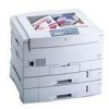
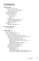
Figures The Phaser 2135 Color Printer with lower tray assembly and lower tray deck 1 Print engine circuit boards 5 Print engine sensor and switch locations 6 Print engine motors, clutches and solenoids 7 Features of the controller board 8 The control panel 9 The printer rear panel 10 Tray switch sensors and actuators 12 Door safety interlock switches 35 Print problem caused by dirty LED lens 83 Removing the top cover 88 Removing the rear cover 89 Removing the front cover 90 Removing the left-side cover 91 Removing the face-up tray 92 Removing the right door. 93 Removing the electrical card cage cooling fan 94 Removing the front power supply fan 95 Removing the rear power supply fan 96 Removing the rear shield plate 97 Removing the electrical card cage 99 Disconnecting the registration motor in-line connector (HOPFF) 100 Removing the printer unit chassis 101 Removing the top shield plate 103 Removing the left plate assembly 104 Removing the system controller board 105 Removing the RAM DIMMs 106 Removing the hard drive 107 Removing the print engine controller 108 Removing the toner sensor board 110 Removing the entrance sensor board 111 Removing the high voltage power supply 113 Removing the low voltage power supply 114 Removing the control panel 115 Removing the feed rollers and nudger roller 116 Removing the feed roller and nudger roller 117 Removing the main feeder assembly 118 Removing the multi-sheet bypass feeder 120 x Phaser 2135 Color Printer
-
 1
1 -
2
-
3
-
4
-
5
-
 6
6 -
 7
7 -
 8
8 -
 9
9 -
 10
10 -
 11
11 -
 12
12 -
 13
13 -
 14
14 -
 15
15 -
 16
16 -
17
-
18
-
19
-
20
-
21
-
22
-
23
-
24
-
25
-
26
-
27
-
28
-
29
-
30
-
31
-
32
-
33
-
34
-
35
-
36
-
37
-
38
-
39
-
40
-
41
-
42
-
43
-
44
-
45
-
46
-
47
-
48
-
49
-
50
-
51
-
52
-
53
-
54
-
55
-
56
-
57
-
58
-
59
-
60
-
61
-
62
-
63
-
64
-
65
-
66
-
67
-
68
-
69
-
70
-
71
-
72
-
73
-
74
-
75
-
76
-
77
-
78
-
79
-
80
-
81
-
82
-
83
-
84
-
85
-
86
-
87
-
88
-
89
-
90
-
91
-
92
-
93
-
94
-
95
-
96
-
97
-
98
-
99
-
100
-
101
-
102
-
103
-
104
-
105
-
106
-
107
-
108
-
109
-
110
-
111
-
112
-
113
-
114
-
115
-
116
-
117
-
118
-
119
-
120
-
121
-
122
-
123
-
124
-
125
-
126
-
127
-
128
-
129
-
130
-
131
-
132
-
133
-
134
-
135
-
136
-
137
-
138
-
139
-
140
-
141
-
142
-
143
-
144
-
145
-
146
-
147
-
148
-
149
-
150
-
151
-
152
-
153
-
154
-
155
-
156
-
157
-
158
-
159
-
160
-
161
-
162
-
163
-
164
-
165
-
166
-
167
-
168
-
169
-
170
-
171
-
172
-
173
-
174
-
175
-
176
-
177
-
178
-
179
-
180
-
181
-
182
-
183
-
184
-
185
-
186
-
187
-
188
-
189
-
190
-
191
-
192
-
193
-
194
-
195
-
196
-
197
-
198
-
199
 |
 |
