Yamaha 500 YMC-700/500 Owners Manual - Page 7
Connections, USB storage device, Power cable, Remote control, Speakers and Subwoofer, Wired network
 |
View all Yamaha 500 manuals
Add to My Manuals
Save this manual to your list of manuals |
Page 7 highlights
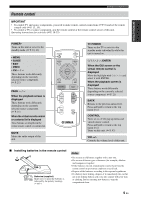
Connections Make sure that this unit and other components are unplugged from the AC wall outlets. Remote control Connect the supplied IR flashers to the REMOTE CONTROL OUT 1 and 2 jacks. y You can attach the IR flashers to any of the components used in conjunction with this unit because the same signal is output from the REMOTE CONTROL OUT 1, 2, and 3 jacks. ☞ P. 8 IR flashers (supplied) Power cable To AC wall outlet Power cable (supplied) USB storage device Be sure to insert in the proper direction. You can connect or disconnect USB storage devices while this unit is turned on. Supported devices ☞ P. 2 Wired network YMoCn-l7y00 Modem WAN LAN Router PC Setup ☞ P. 25, 40 Use CAT-5 or higher STP cable IN OUT 1 USB 3 2 REMOTE CONTROL NETWORK 1 2 AUDIO IN HDMI OUT R3 L AC IN RL RL SUB WOOFER OUTPUT 3 FRONT SURROUND CENTER SPEAKERS Speakers and Subwoofer Speaker cables Subwoofer cable Front Speaker layout ☞ P. 9 Speakers Also refer to the supplied Quick Start Guide. Surround Speakers Center Speaker Subwoofer Caution · Be sure to use speakers with 6 ohm or higher impedance. · Do not let the bare speaker wires touch each other or do not let them touch any metal part of this unit. This could damage this unit and/or speakers. · Be sure to connect the left channel (L), right channel (R), "+" and "-" properly. If the connections are faulty, this unit cannot reproduce the input sources accurately. · If speakers have color coded terminals, match the color. If not, connect the striped (grooved, etc.) cable to the "+" terminals of this unit and your speaker and connect the plain cable to the "-" terminals. 6 En
-
 1
1 -
 2
2 -
 3
3 -
 4
4 -
 5
5 -
 6
6 -
 7
7 -
 8
8 -
 9
9 -
 10
10 -
 11
11 -
 12
12 -
13
-
14
-
15
-
16
-
17
-
18
-
19
-
20
-
21
-
22
-
23
-
24
-
25
-
26
-
27
-
28
-
29
-
30
-
31
-
32
-
33
-
34
-
35
-
36
-
37
-
38
-
39
-
40
-
41
-
42
-
43
-
44
-
45
-
46
-
47
-
48
-
49
-
50
-
51
-
52
-
53
-
54
-
55
-
56
-
57
-
58
-
59
-
60
-
61
 |
 |
