Yamaha 500 YMC-700/500 Owners Manual - Page 9
Remote control connections, Connections, Settings, Operations
 |
View all Yamaha 500 manuals
Add to My Manuals
Save this manual to your list of manuals |
Page 9 highlights
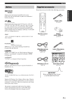
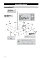
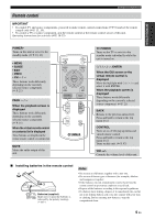
Remote control connections You can control your TV and the components connected to this unit using the remote control of this unit by connecting the IR flashers between this unit and the components, and by setting the IR codes. You can also turn on or off the TV and the components in conjunction with the operation of this unit. TV Note While this unit is turned on, this unit passes all remote control codes (of the TV and source devices) input at the remote control sensor to the TV and the devices via IR flashers. Source device About the remote control codes This unit equips built-in remote control codes for most functions of many audio/video components. The remote control codes can be "learned", assigning them to the remote control of this unit or to the virtual remote control (☞ P. 21). The unit transmits the proper codes to the different devices through the IR flasher. ■ Connections TV SENSOR Peel off the wax paper before attaching the flashers. Source device SENSOR IN OUT 1 USB 3 2 REMOTE CONTROL AC IN R FRONT SPE To other source devices Connect the plugs of the supplied IR flashers to the REMOTE CONTROL OUT 1 and 2 jacks, and attach the flashers to the remote control sensors of your TV and the components connected to this unit. The supplied IR flashers have two flasher heads each. Both flasher heads function equivalently. You can also connect a commercially available flasher to the REMOTE CONTROL OUT 3 jack. y • You can connect the IR flashers to any of the REMOTE CONTROL OUT 1, 2, and 3 jacks because the same signal is output. • Refer to the owner's manual of the TV and source devices for the position of the remote control sensor. ■ Settings Make the following settings. • The IR setting for your TV Initial Setup ☞ P. 10, Setup Menu ☞ P. 42 • The IR settings for the components connected to this unit Initial Setup ☞ P. 10, Setup Menu ☞ P. 39 • Other settings "Initial Screen" menu ☞ P. 43 ■ Operations To control the TV and the components connected to this unit, aim the remote control at the remote control sensor of this unit. Enjoying the contents on an external device ☞ P. 20 About the REMOTE CONTROL IN jack You can connect a commercially available IR receiver to this jack to control this unit even if it is concealed. Place the IR receiver within sight. 8 En
-
 1
1 -
2
-
3
-
 4
4 -
 5
5 -
 6
6 -
 7
7 -
 8
8 -
 9
9 -
 10
10 -
 11
11 -
 12
12 -
 13
13 -
 14
14 -
15
-
16
-
17
-
18
-
19
-
20
-
21
-
22
-
23
-
24
-
25
-
26
-
27
-
28
-
29
-
30
-
31
-
32
-
33
-
34
-
35
-
36
-
37
-
38
-
39
-
40
-
41
-
42
-
43
-
44
-
45
-
46
-
47
-
48
-
49
-
50
-
51
-
52
-
53
-
54
-
55
-
56
-
57
-
58
-
59
-
60
-
61
 |
 |
