Yamaha YAS-706 Owners Manual - Page 8
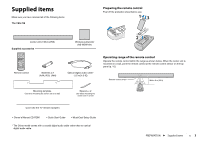
Subwoofer rear panel, Power cable, SUBWOOFER PAIRING key, STATUS indicator, SYSTEM CONNECTOR jack
 |
View all Yamaha YAS-706 manuals
Add to My Manuals
Save this manual to your list of manuals |
Page 8 highlights
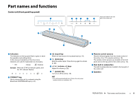
Subwoofer (rear panel) SUBWOOFER PAIRING STATUS SYSTEM INPUT CONNECTOR 2 3 45 SUBWOOFER PAIRING STATUS SYSTEM INPUT CONNECTOR 1 1 Power cable For connecting to an AC wall outlet (p. 14). 2 SUBWOOFER PAIRING key Used to pair the center unit with the subwoofer manually (p. 62). Use a pin or other pointed object to press this key. 3 STATUS indicator Shows subwoofer's connection status (p. 15). Glows green: Power on Glows red: Power off 4 SYSTEM CONNECTOR jack For connecting to the center unit using a wired connection (p. 15). 5 INPUT jack For connecting to the center unit using a wired connection (p. 15). PREPARATION ➤ Part names and functions En 8
-
 1
1 -
2
-
 3
3 -
 4
4 -
 5
5 -
 6
6 -
 7
7 -
 8
8 -
 9
9 -
 10
10 -
 11
11 -
 12
12 -
 13
13 -
14
-
15
-
16
-
17
-
18
-
19
-
20
-
21
-
22
-
23
-
24
-
25
-
26
-
27
-
28
-
29
-
30
-
31
-
32
-
33
-
34
-
35
-
36
-
37
-
38
-
39
-
40
-
41
-
42
-
43
-
44
-
45
-
46
-
47
-
48
-
49
-
50
-
51
-
52
-
53
-
54
-
55
-
56
-
57
-
58
-
59
-
60
-
61
-
62
-
63
-
64
-
65
-
66
-
67
 |
 |

PREPARATION
➤
Part names and functions
En
8
Subwoofer (rear panel)
1
Power cable
For connecting to an AC wall outlet (p. 14).
2
SUBWOOFER PAIRING key
Used to pair the center unit with the subwoofer
manually (p. 62). Use a pin or other pointed object to
press this key.
3
STATUS indicator
Shows subwoofer’s connection status (p. 15).
Glows green: Power on
Glows red: Power off
4
SYSTEM CONNECTOR jack
For connecting to the center unit using a wired
connection (p. 15).
5
INPUT jack
For connecting to the center unit using a wired
connection (p. 15).
SYSTEM
CONNECTOR
SUBWOOFER
PAIRING
INPUT
STATUS
SYSTEM
CONNECTOR
SUBWOOFER
PAIRING
INPUT
STATUS
2
3
4
5
1