Yamaha YRM-103 YRM-103 Owners Manual Image - Page 6
with each component
 |
View all Yamaha YRM-103 manuals
Add to My Manuals
Save this manual to your list of manuals |
Page 6 highlights
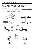
Please refer to the Owner's Manual supplied with your CX5M Music Computer for connecting video display, printer, and cassette recorder. The following diagram is given for easy reference. Please read carefully the Owner's Manual provided with each component before assembling. Caution: Before connecting the system, be sure that the power to all components is turned OFF. Fig. 2 Connection diagram for Audio System and Yamaha DX7 MIDI out terminals (0 /-----ta,.). / dpi Audio output terminals Powered monito speakers FM Sound Synthesizer Unit DX7 (Left-side panel of CX5M) 75 6 5 6 00 if • o • coo 77.7s.aq Yamaha DX7 Audio OUT MIDI IN/OUT Stereo amplifier O • AUX-IN PA speaker u O O twis• Powered mixer SM. LULL 1111 O O O -3-
-
 1
1 -
 2
2 -
 3
3 -
 4
4 -
 5
5 -
 6
6 -
 7
7 -
 8
8 -
 9
9 -
 10
10 -
 11
11 -
 12
12 -
13
-
14
-
15
-
16
-
17
-
18
-
19
-
20
-
21
-
22
-
23
-
24
-
25
-
26
-
27
-
28
-
29
-
30
-
31
-
32
-
33
-
34
-
35
 |
 |

Please
refer
to
the
Owner's
Manual
supplied with
your
CX5M
Music
Computer
for
connecting
video
display,
printer,
and
cassette
recorder.
The
following
diagram
is
given
for
easy reference.
Please
read
carefully
the
Owner's
Manual
provided
with each component
before assembling.
Caution:
Before connecting
the
system,
be
sure
that
the
power
to
all
components is
turned OFF.
Fig.
2
Connection
diagram
for
Audio
System
and
Yamaha
DX7
DX7
MIDI
out
terminals
(0
/-----
,
ta
..
)
/
dp
i
FM
Sound
Synthesizer
Unit
(Left
-side
panel
of
CX5M)
7
5
6
5
6
00
i
f
Yamaha
DX7
Audio
OUT
Audio
output
terminals
MIDI
IN/OUT
PA
speaker
O
O
Powered
monito
speakers
•
o
•
coo
77
.7s.aq
twis•
SM.
LULL
1111
Stereo
amplifier
•
AUX-IN
Powered
mixer
O
O
O
O
-3-