Yamaha i88X Owner's Manual - Page 11
Rear Panel, Output 1 & 2 / Master Out L & R Trs - firewire
 |
View all Yamaha i88X manuals
Add to My Manuals
Save this manual to your list of manuals |
Page 11 highlights
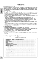
Rear Panel F E English 2 1 M DC IN MIDI DIGITAL STEREO DIGITAL STEREO OPTICAL COAXIAL 8 7 6 5 4 3 INPUT 2 1 INSERT I/O (BAL) OUT IN OUT IN 8 7 6 5 4 3 2/ R 1/ L OUTPUT / MASTER +4dB(BAL) LK JI H G E INSERT I/O 1 & 2 (TRS phone) jacks These unbalanced TRS phone-type 1/4" connectors are used for channel insert ins and outs. Use a split cable to insert an external effects proces- sor to INPUT 1 & 2 (3) on the front panel. INSERT I/O 1 corresponds to INPUT 1, and INSERT I/O 2 to INPUT 2. The pin configuration is shown below. To external processor input To INSERT I/O Sleeve Ring Tip Sleeve Tip To external processor output F INPUT 3-8 (TRS phone) jacks These are TRS phone type 1/4" input jacks (balanced). The nominal input level is -20 dBu through +10 dBu. You can also connect devices such as synthesizers or rhythm machines with unbalanced outputs here. G OUTPUT 1 & 2 / MASTER OUT L & R (TRS phone) jacks These TRS phone type 1/4" output jacks (balanced) output an audio analog signal, which is the combination of mLAN input channels 1 & 2, and audio monitoring output selected via the [SELECT] (7) switch on the front panel. The nominal output level is +4 dBu (pages 16 and 17). H OUTPUT 3-8 (TRS phone) jacks These TRS phone type 1/4" output jacks (balanced) output audio analog signals from mLAN input channels 3-8 respectively. The nominal output level is +4 dBu. I DIGITAL STEREO COAXIAL IN & OUT jacks These coaxial jacks (RCA pin connectors) input and output IEC-60958 consumer format digital audio signals. Connect these jacks to the stereo input and output of a DAT recorder, MD recorder, etc., using RCA pin cables for digital audio. J OPTICAL IN & OUT jacks These optical jacks input and output digital stereo or ADAT audio signals. Use the [OPTICAL SELECT] (A) switch on the front panel to select DIGITAL STEREO, ADAT NORMAL, or ADAT DOUBLE mode. NOTE The coaxial and optical digital stereo input jacks feature a built-in sampling rate converter (SRC), which enables audio signals at different sampling frequencies to be input from connected devices. K MIDI IN & OUT ports Connect MIDI equipment here. These ports enable you to transmit MIDI messages between a computer or mLAN devices in an mLAN network and a MIDI instrument connected to the i88X. L DC IN terminal Connect the included AC adapter (PA-5D) here. WARNING Be sure to use the included adapter. Using an AC adapter other than the PA-5D may cause damage to the i88X, and may even pose a serious electrical shock hazard. Connect the adapter to an AC outlet of the specified voltage. M mLAN 1 & 2 connectors These 6-pin IEEE1394 connectors enable you to connect the i88X to an mLAN device or IEEE1394-compatible (FireWire/i.Link) device. The operation is identical regardless of which connector is used (mLAN 1 or mLAN 2). If the target device has a 4-pin connector, use a commercially available 4-pin to 6-pin IEEE1394 cable. Avoid creating a connection loop (page 23) when connecting the devices. NOTE Yamaha recommends that you use an IEEE1394 cable with a length of 4.5 meters or less. 11
-
 1
1 -
2
-
3
-
4
-
5
-
 6
6 -
 7
7 -
 8
8 -
 9
9 -
 10
10 -
 11
11 -
 12
12 -
 13
13 -
 14
14 -
 15
15 -
 16
16 -
17
-
18
-
19
-
20
-
21
-
22
-
23
-
24
-
25
-
26
-
27
-
28
-
29
-
30
-
31
-
32
-
33
-
34
-
35
-
36
-
37
-
38
-
39
-
40
-
41
-
42
-
43
-
44
-
45
-
46
-
47
-
48
-
49
-
50
-
51
-
52
-
53
-
54
-
55
-
56
-
57
-
58
-
59
-
60
-
61
-
62
-
63
-
64
-
65
-
66
-
67
-
68
-
69
-
70
-
71
-
72
-
73
-
74
-
75
-
76
-
77
-
78
 |
 |
