ZyXEL MGS-3712F User Guide - Page 40
Signal Slot
 |
View all ZyXEL MGS-3712F manuals
Add to My Manuals
Save this manual to your list of manuals |
Page 40 highlights
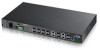
Chapter 3 Hardware Overview 3.1.6 Signal Slot The Signal slot (fitted with the signal connector) allows you to connect devices to the Switch, such as sensors or other ZyXEL switches which support the external alarm feature. This feature is in addition to the system alarm, which detects abnormal temperatures, voltage levels and fan speeds on the Switch. Your Switch can respond to an external signal in four ways. • The ALM LED shows an alert. • The Signal slot can send an external alarm on to another device. By daisy- chaining the signal sensor cables from one Switch to another ZyXEL switch which supports this feature, the external alarm alert (but not the system alarm) is received on each Switch. • The Switch can also be configured to send an SNMP trap to the SNMP server. See Section 34.3 on page 306 for more information on using SNMP. • The Switch can be configured to create an error log of the alarm. See Section 36.1 on page 331 for more information on using the system log. 3.1.6.1 Connect a Sensor to the Signal Slot This section shows you how to connect an external sensor device to the Switch. 1 Use a connector to connect wires of the correct gauge to the sensor's signal output pins. See Chapter 42 on page 357 for the wire specifications. Check the sensor's documentation to identify its two signal output pins. 2 Connect these two wires to any one of the following pairs of signal input pins on the Switch's Signal connector - (4,5) (6,7) (8,9) (10,11). The pin numbers run from the right side of the connector to the left. 2a Connect each of the sensor's two signal output wires to the Signal connector by depressing the spring clip corresponding to the pin you are connecting to. 2b Insert the wire and release the spring clip. 2c Repeat the process for the sensor's other signal output wire. A total of four sensors may be connected to the Signal connector in this way using the remaining signal input pins. 40 MGS-3712/MGS-3712F User's Guide
-
 1
1 -
2
-
3
-
4
-
5
-
6
-
7
-
8
-
9
-
10
-
11
-
12
-
13
-
14
-
15
-
16
-
17
-
18
-
19
-
20
-
21
-
22
-
23
-
24
-
25
-
26
-
27
-
28
-
29
-
30
-
31
-
32
-
33
-
34
-
 35
35 -
 36
36 -
 37
37 -
 38
38 -
 39
39 -
 40
40 -
 41
41 -
 42
42 -
 43
43 -
 44
44 -
 45
45 -
46
-
47
-
48
-
49
-
50
-
51
-
52
-
53
-
54
-
55
-
56
-
57
-
58
-
59
-
60
-
61
-
62
-
63
-
64
-
65
-
66
-
67
-
68
-
69
-
70
-
71
-
72
-
73
-
74
-
75
-
76
-
77
-
78
-
79
-
80
-
81
-
82
-
83
-
84
-
85
-
86
-
87
-
88
-
89
-
90
-
91
-
92
-
93
-
94
-
95
-
96
-
97
-
98
-
99
-
100
-
101
-
102
-
103
-
104
-
105
-
106
-
107
-
108
-
109
-
110
-
111
-
112
-
113
-
114
-
115
-
116
-
117
-
118
-
119
-
120
-
121
-
122
-
123
-
124
-
125
-
126
-
127
-
128
-
129
-
130
-
131
-
132
-
133
-
134
-
135
-
136
-
137
-
138
-
139
-
140
-
141
-
142
-
143
-
144
-
145
-
146
-
147
-
148
-
149
-
150
-
151
-
152
-
153
-
154
-
155
-
156
-
157
-
158
-
159
-
160
-
161
-
162
-
163
-
164
-
165
-
166
-
167
-
168
-
169
-
170
-
171
-
172
-
173
-
174
-
175
-
176
-
177
-
178
-
179
-
180
-
181
-
182
-
183
-
184
-
185
-
186
-
187
-
188
-
189
-
190
-
191
-
192
-
193
-
194
-
195
-
196
-
197
-
198
-
199
-
200
-
201
-
202
-
203
-
204
-
205
-
206
-
207
-
208
-
209
-
210
-
211
-
212
-
213
-
214
-
215
-
216
-
217
-
218
-
219
-
220
-
221
-
222
-
223
-
224
-
225
-
226
-
227
-
228
-
229
-
230
-
231
-
232
-
233
-
234
-
235
-
236
-
237
-
238
-
239
-
240
-
241
-
242
-
243
-
244
-
245
-
246
-
247
-
248
-
249
-
250
-
251
-
252
-
253
-
254
-
255
-
256
-
257
-
258
-
259
-
260
-
261
-
262
-
263
-
264
-
265
-
266
-
267
-
268
-
269
-
270
-
271
-
272
-
273
-
274
-
275
-
276
-
277
-
278
-
279
-
280
-
281
-
282
-
283
-
284
-
285
-
286
-
287
-
288
-
289
-
290
-
291
-
292
-
293
-
294
-
295
-
296
-
297
-
298
-
299
-
300
-
301
-
302
-
303
-
304
-
305
-
306
-
307
-
308
-
309
-
310
-
311
-
312
-
313
-
314
-
315
-
316
-
317
-
318
-
319
-
320
-
321
-
322
-
323
-
324
-
325
-
326
-
327
-
328
-
329
-
330
-
331
-
332
-
333
-
334
-
335
-
336
-
337
-
338
-
339
-
340
-
341
-
342
-
343
-
344
-
345
-
346
-
347
-
348
-
349
-
350
-
351
-
352
-
353
-
354
-
355
-
356
-
357
-
358
-
359
-
360
-
361
-
362
-
363
-
364
-
365
-
366
-
367
-
368
-
369
-
370
-
371
-
372
-
373
-
374
-
375
-
376
-
377
-
378
-
379
-
380
-
381
-
382
 |
 |
