2008 BMW M6 Owner's Manual - Page 221
2008 BMW M6 Manual

Page 221 highlights
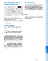
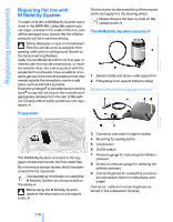
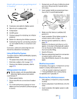
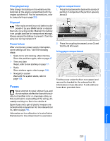
Model with pressure gauge integrated in housing* 4. Screw dust cap off valve of defective wheel and screw filling hose 2 of sealant bottle onto valve. 5. Insert sealant bottle on compressor housing so that it is positioned upright. 3 4 5 6 7 8 9 Connector and cable for lighter socket Compressor On/Off switch Pressure gauge for indicating tire inflation pressure Button for reducing tire inflation pressure Connecting hose for connecting compressor and sealant bottle or compressor and wheel 6. Make sure that device is switched off, position 0. 7. Insert connector 3 into lighter socket in vehicle interior, refer to page 112. 8. With the ignition switched on, refer to page 59: Switch on the device and allow to run for approx. 3 minutes to fill wheel with sealant. It is not important what inflation pressure the tire has after filling. 9. Switch off device. 10. Remove connecting hose from connection of sealant bottle and tire valve. Stow the M Mobility System in the vehicle again. Driving tips Reference Mobility Communications Entertainment Navigation Mounting for sealing bottle Connector, cable and connecting hose are stored on underside of compressor. Using M Mobility System To repair a flat tire with the M Mobility System, proceed as follows: > Fill sealant into wheel, refer to page 219. > Distribute sealant, refer to page 219. > Produce tire inflation pressure, refer to page 219. Distributing sealant Immediately drive approx. 2 miles/3 km so that sealant is evenly distributed in tire. Do not exceed a maximum speed of 35 mph/60 km/h. Do not drop below 12 mph/20 km/h if possible.< Filling sealant into wheel Strictly comply with the specified order, otherwise highly pressurized sealant could escape.< 1. Shake sealant bottle. 2. Screw hose 9 onto connection of sealant bottle. 3. For model with pressure gauge on hose: Make sure that screw 8 on pressure gauge is closed. Producing tire inflation pressure 1. After approx. 2 miles/3 km, stop at suitable location. 2. Screw compressor hose 9 directly onto tire valve. 3. Insert connector 3 in lighter socket in vehicle interior. 219 Online Edition for Part no. 01 41 0 014 244 - © 08/07 BMW AG Controls At a glance
-
 1
1 -
2
-
3
-
4
-
5
-
6
-
7
-
8
-
9
-
10
-
11
-
12
-
13
-
14
-
15
-
16
-
17
-
18
-
19
-
20
-
21
-
22
-
23
-
24
-
25
-
26
-
27
-
28
-
29
-
30
-
31
-
32
-
33
-
34
-
35
-
36
-
37
-
38
-
39
-
40
-
41
-
42
-
43
-
44
-
45
-
46
-
47
-
48
-
49
-
50
-
51
-
52
-
53
-
54
-
55
-
56
-
57
-
58
-
59
-
60
-
61
-
62
-
63
-
64
-
65
-
66
-
67
-
68
-
69
-
70
-
71
-
72
-
73
-
74
-
75
-
76
-
77
-
78
-
79
-
80
-
81
-
82
-
83
-
84
-
85
-
86
-
87
-
88
-
89
-
90
-
91
-
92
-
93
-
94
-
95
-
96
-
97
-
98
-
99
-
100
-
101
-
102
-
103
-
104
-
105
-
106
-
107
-
108
-
109
-
110
-
111
-
112
-
113
-
114
-
115
-
116
-
117
-
118
-
119
-
120
-
121
-
122
-
123
-
124
-
125
-
126
-
127
-
128
-
129
-
130
-
131
-
132
-
133
-
134
-
135
-
136
-
137
-
138
-
139
-
140
-
141
-
142
-
143
-
144
-
145
-
146
-
147
-
148
-
149
-
150
-
151
-
152
-
153
-
154
-
155
-
156
-
157
-
158
-
159
-
160
-
161
-
162
-
163
-
164
-
165
-
166
-
167
-
168
-
169
-
170
-
171
-
172
-
173
-
174
-
175
-
176
-
177
-
178
-
179
-
180
-
181
-
182
-
183
-
184
-
185
-
186
-
187
-
188
-
189
-
190
-
191
-
192
-
193
-
194
-
195
-
196
-
197
-
198
-
199
-
200
-
201
-
202
-
203
-
204
-
205
-
206
-
207
-
208
-
209
-
210
-
211
-
212
-
213
-
214
-
215
-
 216
216 -
 217
217 -
 218
218 -
 219
219 -
 220
220 -
 221
221 -
 222
222 -
 223
223 -
 224
224 -
 225
225 -
 226
226 -
227
-
228
-
229
-
230
-
231
-
232
-
233
-
234
-
235
-
236
-
237
-
238
-
239
-
240
-
241
-
242
-
243
-
244
-
245
-
246
-
247
-
248
-
249
-
250
-
251
-
252
-
253
-
254
-
255
-
256
-
257
-
258
-
259
-
260
-
261
-
262
 |
 |
