2011 Mercedes GLK-Class Owner's Manual - Page 254
2011 Mercedes GLK-Class Manual
Page 254 highlights
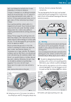
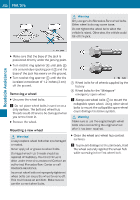
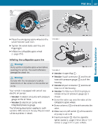
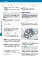
252 X Flat tire Make sure that the key is in position 1(Y page 129) in the ignition lock. X Press on/off switch ; on the electric air pump to I. The electric air pump is switched on. The tire is inflated. X Version 2: stow connector = and the air hose in the lower section of the pump housing. X Stow the electric air pump in the designated place in the vehicle. G Warning Lowering the vehicle G Warning! Pump up the collapsible spare wheel before lowering the vehicle. You could otherwise damage the wheel rim. X The air hose and the union nut can become hot during inflation. Exercise proper caution to avoid burning yourself when using the equipment. ! Do not operate the electric air pump for longer than eight minutes at a time without a break. It may otherwise overheat. The air pump can be operated again once it has cooled down. X Inflate the tires to the prescribed tire pressure. The prescribed tire pressure is stated on the yellow sticker which is affixed to emergency spare wheel. X When the prescribed tire pressure has been attained, press on/off switch 2 on the electric air pump to 0. The electric air pump is switched off. X Turn the key to position 0 in the ignition lock. X Roadside Assistance Place the ratchet ring spanner onto the hexagon nut of the jack so that the letters AB are visible. X Turn the ratchet ring spanner until the vehicle is once again standing firmly on the ground. X Place the jack to one side. Version 1: if the tire pressure is higher than specified, open the pressure release screw on pressure gauge 4 until the correct tire pressure is set. X Version 2: if the tire pressure is higher than specified, press pressure release button 6 until the correct tire pressure is set. X Unscrew union nut A of the air hose from the valve. X Screw the valve cap onto the valve of the collapsible spare wheel again. X Version 1: stow connector = and the air hose behind flap :. X Tighten the wheel bolts evenly in a crosswise pattern in the sequence indicated (: to A). The tightening torque must be 110 lb-ft (150 Nm). G Warning! Have the tightening torque checked immediately after a wheel is changed. The wheels could come loose if they are not tightened to a torque of 110 lb-ft (150 Nm). X Turn the jack back to its initial position and store it together with the rest of the vehicle tool kit in the cargo compartment.
-
 1
1 -
2
-
3
-
4
-
5
-
6
-
7
-
8
-
9
-
10
-
11
-
12
-
13
-
14
-
15
-
16
-
17
-
18
-
19
-
20
-
21
-
22
-
23
-
24
-
25
-
26
-
27
-
28
-
29
-
30
-
31
-
32
-
33
-
34
-
35
-
36
-
37
-
38
-
39
-
40
-
41
-
42
-
43
-
44
-
45
-
46
-
47
-
48
-
49
-
50
-
51
-
52
-
53
-
54
-
55
-
56
-
57
-
58
-
59
-
60
-
61
-
62
-
63
-
64
-
65
-
66
-
67
-
68
-
69
-
70
-
71
-
72
-
73
-
74
-
75
-
76
-
77
-
78
-
79
-
80
-
81
-
82
-
83
-
84
-
85
-
86
-
87
-
88
-
89
-
90
-
91
-
92
-
93
-
94
-
95
-
96
-
97
-
98
-
99
-
100
-
101
-
102
-
103
-
104
-
105
-
106
-
107
-
108
-
109
-
110
-
111
-
112
-
113
-
114
-
115
-
116
-
117
-
118
-
119
-
120
-
121
-
122
-
123
-
124
-
125
-
126
-
127
-
128
-
129
-
130
-
131
-
132
-
133
-
134
-
135
-
136
-
137
-
138
-
139
-
140
-
141
-
142
-
143
-
144
-
145
-
146
-
147
-
148
-
149
-
150
-
151
-
152
-
153
-
154
-
155
-
156
-
157
-
158
-
159
-
160
-
161
-
162
-
163
-
164
-
165
-
166
-
167
-
168
-
169
-
170
-
171
-
172
-
173
-
174
-
175
-
176
-
177
-
178
-
179
-
180
-
181
-
182
-
183
-
184
-
185
-
186
-
187
-
188
-
189
-
190
-
191
-
192
-
193
-
194
-
195
-
196
-
197
-
198
-
199
-
200
-
201
-
202
-
203
-
204
-
205
-
206
-
207
-
208
-
209
-
210
-
211
-
212
-
213
-
214
-
215
-
216
-
217
-
218
-
219
-
220
-
221
-
222
-
223
-
224
-
225
-
226
-
227
-
228
-
229
-
230
-
231
-
232
-
233
-
234
-
235
-
236
-
237
-
238
-
239
-
240
-
241
-
242
-
243
-
244
-
245
-
246
-
247
-
248
-
 249
249 -
 250
250 -
 251
251 -
 252
252 -
 253
253 -
 254
254 -
 255
255 -
 256
256 -
 257
257 -
 258
258 -
 259
259 -
260
-
261
-
262
-
263
-
264
-
265
-
266
-
267
-
268
-
269
-
270
-
271
-
272
-
273
-
274
-
275
-
276
-
277
-
278
-
279
-
280
-
281
-
282
-
283
-
284
-
285
-
286
-
287
-
288
-
289
-
290
-
291
-
292
-
293
-
294
-
295
-
296
-
297
-
298
-
299
-
300
-
301
-
302
-
303
-
304
 |
 |
