3Com 3812 Getting Started Guide - Page 23
The Power-up Sequence, Powering-up the Switch, Checking for Correct Operation of LEDs - self test
 |
UPC - 662705470191
View all 3Com 3812 manuals
Add to My Manuals
Save this manual to your list of manuals |
Page 23 highlights
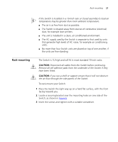
The Power-up Sequence 23 The Power-up Sequence The following sections describe how to get your Switch powered-up and ready for operation. Powering-up the Use the following sequence of steps to power-up the Switch. Switch 1 Plug the power cord into the power socket at the rear of the Switch. 2 Plug the other end of the power cord into your power outlet. The Switch powers-up and runs through its Power On Self Test (POST), which takes approximately 1 minute. Checking for Correct During the Power On Self Test, all ports on the Switch are disabled and Operation of LEDs the LEDs light in a rapid sequence. When the POST has completed, check the Unit Status to make sure that your Switch is operating correctly. Table 6 shows possible colors for the LED. Table 6 Unit Status Colors Color Green Yellow Off State The Switch is powered-up and operating normally. The Switch has failed its Power On Self Test (POST). The Switch is not receiving power. If there is evidence of a problem, see "Solving Problems Indicated by LEDs" on page 46 for a list of suggested solutions. CAUTION: The Switch has no ON/OFF switch; the only method of connecting or disconnecting mains power is by connecting or disconnecting the power cord. Connecting a Redundant Power Supply (Switch 3848 only) You can connect a SuperStack 3 Advance Redundant Power System to the Switch 3848. This unit, which is also known as RPS, is designed to maintain the power to your Switch if a power supply failure occurs. For normal redundancy, the unit requires a Type 3 Power Module (part number 3C16075)
-
 1
1 -
2
-
3
-
4
-
5
-
6
-
7
-
8
-
9
-
10
-
11
-
12
-
13
-
14
-
15
-
16
-
17
-
 18
18 -
 19
19 -
 20
20 -
 21
21 -
 22
22 -
 23
23 -
 24
24 -
 25
25 -
 26
26 -
 27
27 -
 28
28 -
29
-
30
-
31
-
32
-
33
-
34
-
35
-
36
-
37
-
38
-
39
-
40
-
41
-
42
-
43
-
44
-
45
-
46
-
47
-
48
-
49
-
50
-
51
-
52
-
53
-
54
-
55
-
56
-
57
-
58
-
59
-
60
-
61
-
62
-
63
-
64
-
65
-
66
-
67
-
68
-
69
-
70
-
71
-
72
 |
 |
