3Com 3824 Implementation Guide - Page 37
How STP Works, STP Requirements - us open
 |
UPC - 662705467528
View all 3Com 3824 manuals
Add to My Manuals
Save this manual to your list of manuals |
Page 37 highlights
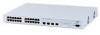
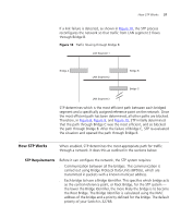
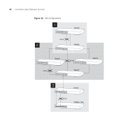
How STP Works 37 If a link failure is detected, as shown in Figure 10, the STP process reconfigures the network so that traffic from LAN segment 2 flows through Bridge B. Figure 10 Traffic flowing through Bridge B STP determines which is the most efficient path between each bridged segment and a specifically assigned reference point on the network. Once the most efficient path has been determined, all other paths are blocked. Therefore, in Figure 8, Figure 9, and Figure 10, STP initially determined that the path through Bridge C was the most efficient, and so blocked the path through Bridge B. After the failure of Bridge C, STP re-evaluated the situation and opened the path through Bridge B. How STP Works When enabled, STP determines the most appropriate path for traffic through a network. It does this as outlined in the sections below. STP Requirements Before it can configure the network, the STP system requires: ■ Communication between all the bridges. This communication is carried out using Bridge Protocol Data Units (BPDUs), which are transmitted in packets with a known multicast address. ■ Each bridge to have a Bridge Identifier. This specifies which bridge acts as the central reference point, or Root Bridge, for the STP system - the lower the Bridge Identifier, the more likely the bridge is to become the Root Bridge. The Bridge Identifier is calculated using the MAC address of the bridge and a priority defined for the bridge. The default priority of your Switch is 32768.
-
 1
1 -
2
-
3
-
4
-
5
-
6
-
7
-
8
-
9
-
10
-
11
-
12
-
13
-
14
-
15
-
16
-
17
-
18
-
19
-
20
-
21
-
22
-
23
-
24
-
25
-
26
-
27
-
28
-
29
-
30
-
31
-
 32
32 -
 33
33 -
 34
34 -
 35
35 -
 36
36 -
 37
37 -
 38
38 -
 39
39 -
 40
40 -
 41
41 -
 42
42 -
43
-
44
-
45
-
46
-
47
-
48
-
49
-
50
-
51
-
52
-
53
-
54
-
55
-
56
-
57
-
58
-
59
-
60
-
61
-
62
-
63
-
64
-
65
-
66
-
67
-
68
-
69
-
70
-
71
-
72
-
73
-
74
-
75
-
76
-
77
-
78
-
79
-
80
-
81
-
82
-
83
-
84
-
85
-
86
-
87
-
88
-
89
-
90
-
91
-
92
-
93
-
94
-
95
-
96
-
97
-
98
-
99
-
100
-
101
-
102
 |
 |