3Com 3CR16708-91 Getting Started Guide - Page 26
Checking for Correct Operation of LEDs, Using Power over Ethernet
 |
UPC - 662705487151
View all 3Com 3CR16708-91 manuals
Add to My Manuals
Save this manual to your list of manuals |
Page 26 highlights
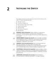
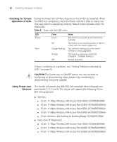
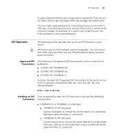
26 CHAPTER 2: INSTALLING THE SWITCH Checking for Correct Operation of LEDs During the Power On Self Test, all ports on the Switch are disabled. When the POST has completed, check the Power and Alert LEDs to make sure that your Switch is operating correctly. Table 6 shows possible colors for these LEDs. Table 6 Power and Alert LED colors LED Power Alert Color Green Off Orange flashing Orange Off State The Switch is powered-up and operating normally. The Switch is not receiving power or there is a fault with the Power Supply Unit. The Switch is starting up or the Switch software is being upgraded. The Switch is reporting a fault (see Chapter 4, "Problem Solving"). Normal operation. If there is evidence of a problem, see "Solving Problems Indicated by LEDs" on page 52. CAUTION The Switch has no ON/OFF switch; the only method of connecting or disconnecting mains power is by connecting or disconnecting the power adapter. Using Power over Ethernet The Switch can power any IEEE 802.3af compliant device through rear panel ports 1, 2, 5 and 6. The Switch will support the following 3Com 802.3af equipment: ■ Wireless: ■ 3Com 11 Mbps Wireless LAN Access Point 8000 (3CRWE80096B) ■ 3Com 11 Mbps Wireless LAN Access Point 8200 (3CRWE820096A) ■ 3Com 11 Mbps Wireless LAN Access Point 8500 (3CRWE850096A) ■ 3Com 11 Mbps Wireless LAN Access Point 8700 (3CRWE870096A) ■ 3Com Wireless LAN Building to Building Bridge (3CRWE91096B) ■ Voice Over IP Telephones: ■ 3Com 11 Mbps Wireless LAN Access Point 8000 (3CRWE80096B) ■ 3Com 11 Mbps Wireless LAN Access Point 8200 (3CRWE820096A) ■ 3Com 11 Mbps Wireless LAN Access Point 8500 (3CRWE850096A)
-
 1
1 -
2
-
3
-
4
-
5
-
6
-
7
-
8
-
9
-
10
-
11
-
12
-
13
-
14
-
15
-
16
-
17
-
18
-
19
-
20
-
 21
21 -
 22
22 -
 23
23 -
 24
24 -
 25
25 -
 26
26 -
 27
27 -
 28
28 -
 29
29 -
 30
30 -
 31
31 -
32
-
33
-
34
-
35
-
36
-
37
-
38
-
39
-
40
-
41
-
42
-
43
-
44
-
45
-
46
-
47
-
48
-
49
-
50
-
51
-
52
-
53
-
54
-
55
-
56
-
57
-
58
-
59
-
60
-
61
-
62
-
63
-
64
-
65
-
66
-
67
-
68
-
69
-
70
-
71
-
72
-
73
-
74
-
75
-
76
-
77
-
78
-
79
-
80
 |
 |