AIWA CX-NA30 Operating Instructions - Page 22
Specifications
 |
View all AIWA CX-NA30 manuals
Add to My Manuals
Save this manual to your list of manuals |
Page 22 highlights
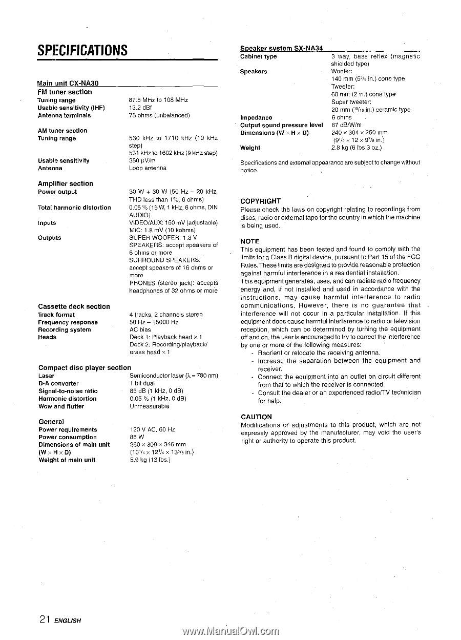
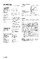
SPECIFICATIONS Main unit CX-NA30 FM tuner section Tuning range Usable sensitivity (IHF) Antenna terminals 87.5 MHz to 108 MHz 13,2 dBf 75 ohms (unbalanced) AM tuner section Tuning range Usable sensitivity Antenna 530 kHz tO 1710 kHz (10 kHz step) 531 kHz to 1602 kHz (9 kHz step) 350 pVlm Loop antenna Amplifier section Power output Total harmonic distortion Inputs outputs 30 W + 30 W (50 HZ -20 kHz, THD less than 1%, 6 ohms) 0.05% (15W, 1 kHz, 6ohms, DIN AUDIO) VI DEO/AUX: 150 mV (adjustable) MIC: 1.8 mV (10 kohms) SUPER WOOFER: 1,3 V SPEAKERS: accept speakers of 6 ohms or more SURROUND SPEAKERS: accept speakers of 16 ohms or more PHONES (stereo jack): accepts headphones of 32 ohms or more Cassette deck section Track format Frequency response Recording system Heads 4 tracks, 2 channels stereo 50 Hz - 15000 HZ AC bias Deck 1: Playback head x 1 Deck 2: Recording/playback/ erase head x 1 Compact disc player section Laser Semiconductor laser (?L= 780 nm) D-A converter 1 bit dual Signal-to-noise ratio 85 dB (1 kHz, O dB) Harmonic distortion 0.05 % (1 kHz, O dB) Wow and flutter Unmeasurable General Power requirements Power consumption Dimensions of main unit (W XHXD) Weight of main unit 120 V AC, 60 Hz 88 w 260 x 309 x 346 mm (10'/4 x 121/4 X 135/8 in.) 5.9 kg (13 Ibs.) Speaker svstem SX-NA34 Cabinet type Speakers lm~edance Output sound pressure level Dimensions (W x H x D) 3 way, bass reflex (magnetic shielded type) Woofer: 140 mm (55/8 in.) Cone type Tweeter: 60 mm (2 in,) cone type Super tweeter: 20 mm ('3/16in.) ceramic type 6 ohms 87 dBIWlm 240 x 304x 250 mm (91/2 X 12x 97/8 in,) 2.8 kg (6 Ibs 3 OZ.) Specifications and external appearance are subject to change without notice. COPYRIGHT Please check the laws on copyright relating to recordings from discs, radio or external tape for the country in which the machine is being used. NOTE This equipment has been tested and found to comply with the limits for a Class B digital device, pursuant to Part 15 of the FCC Rules. These limits are designed to provide reasonable protection against harmful interference in a residential installation. This equipment generates, uses, and can radiate radio frequency energy and, if not installed and used in accordance with the instructions, may cause harmful interference to radio communications. However, there is no guarantee that interference will not occur in a particular installation. If this equipment does cause harmful interference to radio or television reception, which can be determined by turning the equipment off and on, the user is encouraged to try to correct the interference by one or more of the following measures: - Reorient or relocate the receiving antenna. Increase the separation between the equipment and receiver. Connect the equipment into an outlet on circuit different from that to which the receiver is connected. Consult the dealer or an experienced radio/TV technician for help. CAUTION Modifications or adjustments to this product, which are not expressly approved by the manufacturer, may void the user's right or authority to operate this product. 2 I ENGLISH
-
 1
1 -
2
-
3
-
4
-
5
-
6
-
7
-
8
-
9
-
10
-
11
-
12
-
13
-
14
-
15
-
16
-
 17
17 -
 18
18 -
 19
19 -
 20
20 -
 21
21 -
 22
22 -
 23
23 -
 24
24 -
 25
25 -
 26
26 -
 27
27 -
28
-
29
-
30
-
31
-
32
-
33
-
34
-
35
-
36
-
37
-
38
-
39
-
40
-
41
-
42
-
43
-
44
-
45
-
46
-
47
-
48
-
49
-
50
-
51
-
52
-
53
-
54
-
55
-
56
-
57
-
58
-
59
-
60
-
61
-
62
-
63
-
64
-
65
-
66
-
67
-
68
 |
 |