Acer F7200 User Manual - Page 13
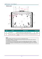
Rear view
 |
View all Acer F7200 manuals
Add to My Manuals
Save this manual to your list of manuals |
Page 13 highlights
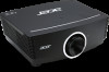
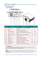
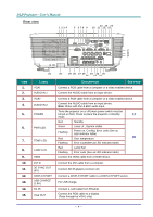
Rear view 1 234 12 14 16 5 6 7 8 9 10 11 13 15 17 18 19 ITEM 1. 2. 3. 4. 5. 6. 7. 8. 9. 10. 11. 12. 13. 14. 15. 31 LABEL VGA1 AUDIO IN 1 VGA2 AUDIO IN 2 POWER PWR LED TEMP LED LAMP LED HDMI DVI-D 3D SYNC OUT (5V) DISPLAYPORT USB CHARGE (1.5A) RJ-45 VGA OUT 30 29 28 27 26 24 22 20 25 23 21 DESCRIPTION SEE PAGE Connect a RGB cable from a computer or a video enabled device. Connect the AUDIO cable from an input device. Connect a RGB cable from a computer or a video enabled device. Connect the AUDIO cable from an input device. Note: Share with DVI & BNC audio input. Turns the projector on or off (main power switch must be turned on first). Press to place the projector in standby 13 mode. Red Standby Green Lamp Lit , System stable Flashing Power on, Cooling, Error code (See as LED indicator table) Red Over temperature 56 Flashing Error Code(See as LED indicator table) Red Lamp Fail Flashing Error code (See as LED indicator table) Connect the HDMI cable from a HDMI device. Connect the DVI cable from a computer. Connect 3D IR glasses receiver unit. Connect a DISPLAYPORT cable to a DISPLAYPORT source. For USB charge. Connect a LAN cable from Ethernet. Connect the RGB cable to a display. (Pass through by VGA1 only) - 4 -
-
 1
1 -
2
-
3
-
4
-
5
-
6
-
7
-
 8
8 -
 9
9 -
 10
10 -
 11
11 -
 12
12 -
 13
13 -
 14
14 -
 15
15 -
 16
16 -
 17
17 -
 18
18 -
19
-
20
-
21
-
22
-
23
-
24
-
25
-
26
-
27
-
28
-
29
-
30
-
31
-
32
-
33
-
34
-
35
-
36
-
37
-
38
-
39
-
40
-
41
-
42
-
43
-
44
-
45
-
46
-
47
-
48
-
49
-
50
-
51
-
52
-
53
-
54
-
55
-
56
-
57
-
58
-
59
-
60
-
61
-
62
-
63
-
64
-
65
-
66
-
67
-
68
-
69
-
70
-
71
-
72
-
73
-
74
-
75
-
76
-
77
 |
 |
