Acer F7200 User Manual - Page 15
Bottom view
 |
View all Acer F7200 manuals
Add to My Manuals
Save this manual to your list of manuals |
Page 15 highlights
Bottom view ITEM 1. 2. LABEL Tilt adjustor Ceiling support holes DESCRIPTION SEE PAGE Rotate adjuster lever to adjust angle position. 15 Contact your dealer for information on mounting the projector on a ceiling Note: When installing, ensure that you use only UL Listed ceiling mounts. For ceiling installations, use approved mounting hardware and M4 screws with a maximum screw depth of 12 mm (0.47 inch). The construction of the ceiling mount must be of a suitable shape and strength. The ceiling mount load capacity must exceed the weight of the installed equipment, and as an additional precaution be capable of withstanding three times the weight of the equipment over a period of 60 seconds. - 6 -
-
 1
1 -
2
-
3
-
4
-
5
-
6
-
7
-
8
-
9
-
 10
10 -
 11
11 -
 12
12 -
 13
13 -
 14
14 -
 15
15 -
 16
16 -
 17
17 -
 18
18 -
 19
19 -
 20
20 -
21
-
22
-
23
-
24
-
25
-
26
-
27
-
28
-
29
-
30
-
31
-
32
-
33
-
34
-
35
-
36
-
37
-
38
-
39
-
40
-
41
-
42
-
43
-
44
-
45
-
46
-
47
-
48
-
49
-
50
-
51
-
52
-
53
-
54
-
55
-
56
-
57
-
58
-
59
-
60
-
61
-
62
-
63
-
64
-
65
-
66
-
67
-
68
-
69
-
70
-
71
-
72
-
73
-
74
-
75
-
76
-
77
 |
 |
—
6
—
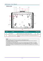
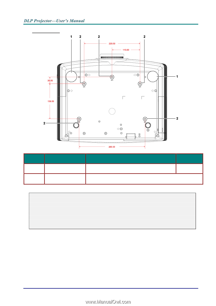
Bottom view
I
TEM
L
ABEL
D
ESCRIPTION
S
EE PAGE
1.
Tilt adjustor
Rotate adjuster lever to adjust angle position.
15
2.
Ceiling support holes
Contact your dealer for information on mounting the projector on a
ceiling
Note:
When installing, ensure that you use only UL Listed ceiling mounts.
For ceiling installations, use approved mounting hardware and M4 screws with a maximum
screw depth of 12 mm (0.47 inch).
The construction of the ceiling mount must be of a suitable shape and strength. The ceiling
mount load capacity must exceed the weight of the installed equipment, and as an additional
precaution be capable of withstanding three times the weight of the equipment over a period of
60 seconds.