Asus CUV4X-E CUV4X-E User Manual - Page 15
ASUS CUV4X-E User's Manual, Motherboard Settings, Expansion Slots/Sockets, Connectors - power
 |
UPC - 610839878079
View all Asus CUV4X-E manuals
Add to My Manuals
Save this manual to your list of manuals |
Page 15 highlights
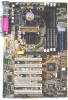
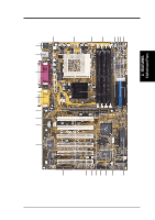
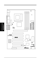
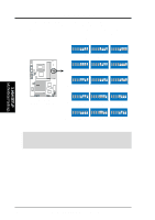
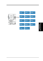
3. H/W SETUP Layout Contents 3. HARDWARE SETUP 3.2 Layout Contents Motherboard Settings 1) JEN p. 17 JumperFree Mode Setting 2) DIP_SW 5-8 p. 18 CPU External Frequency Selection 3) DIP_SW 1-4 p. 19 CPU Core:BUS Frequency Multiple Selection 4) CLRTC p. 21 Clear RTC RAM 5) USBPWR0/1 p. 22 USB Wake-up Jumpers Expansion Slots/Sockets 1) DIMM 1/2/3/4 p. 24 System Memoy Support 2) Socket 370 p. 25 CPU Support 3) PCI 1/2/3/4/5/6 p. 27 32-bit PCI Bus Expansion Slots 4) AGP Pro p. 29 Accelerated Graphics Port 5) AMR p. 30 Audio Modem Riser (AMR) Slot Connectors 1) PS2KBMS p. 31 PS/2 Mouse Port Connector (6-pin female) 2) PS2KBMS p. 31 PS/2 Keyboard Port Connector (6-pin female) 3) USB p. 32 Universal Serial Bus Connectors 1 & 2 (two 4-pin female) 4) PRINTER p. 32 Parallel Port Connector (25-pin female) 5) COM1/COM2 p. 32 Serial Port Connectors (two 9-pin /10-1 pin male) 6) GAME_AUDIO p. 33 Game/MIDI Connector (15-pin female) 7) AUDIO p. 33 Audio Connectors (three 1/8" jacks) 8) IDELED p. 34 IDE Activity LED (2-pin) 9) FLOPPY p. 34 Floppy Disk Drive Port Connector (34-1 pin) 10) PRIMARY IDE p. 35 IDE Connectors (two 40-1 pin) SECONDARY IDE 11) WOL_CON p. 36 Wake-On-LAN Connector (3-pin) 12) WOR p. 36 Wake-On-Ring Connector (2-pin) 13) CPU/PWR/CHA_FAN p. 37 Chassis and CPU Fan Connectors (three3-pin) 14) CHASSIS p. 38 Chassis Intrusion Lead (4-1 pin) 15) SMB p. 38 SMBus Connector (5-1 pin) 16) IR p. 39 Infrared Module Connector (5-pin) 17) USBPORT p. 39 USB Header (10-1 pin) 18) ATXPWR p. 40 ATX Power Supply Connectors (20-pin) 19) AFPANEL p. 41 ASUS iPanel Connector (12-1 pin) 20) MIC2 p. 41 Internal Microphone Connector (3-pin) 21) CD/AUX/MODEM p. 42 Internal Audio Connectors (three 3-pin) 22) PWR.LED (PANEL) p. 43 System Power LED Lead (3-pins) 23) SPEAKER (PANEL) p. 43 System Warning Speaker Connector (4-pin) 24) MSG.LED (PANEL) p. 43 System Message LED (2-pin) 25) SMI (PANEL) p. 43 System Management Interrupt Lead (2-pin) 26) PWR.SW (PANEL) p. 43 ATX / Soft-Off Switch Lead (2-pin) 27) RESET (PANEL) p. 43 Reset Switch Lead (2-pin) ASUS CUV4X-E User's Manual 15
-
 1
1 -
2
-
3
-
4
-
5
-
6
-
7
-
8
-
9
-
 10
10 -
 11
11 -
 12
12 -
 13
13 -
 14
14 -
 15
15 -
 16
16 -
 17
17 -
 18
18 -
 19
19 -
 20
20 -
21
-
22
-
23
-
24
-
25
-
26
-
27
-
28
-
29
-
30
-
31
-
32
-
33
-
34
-
35
-
36
-
37
-
38
-
39
-
40
-
41
-
42
-
43
-
44
-
45
-
46
-
47
-
48
-
49
-
50
-
51
-
52
-
53
-
54
-
55
-
56
-
57
-
58
-
59
-
60
-
61
-
62
-
63
-
64
-
65
-
66
-
67
-
68
-
69
-
70
-
71
-
72
-
73
-
74
-
75
-
76
-
77
-
78
-
79
-
80
-
81
-
82
-
83
-
84
-
85
-
86
-
87
-
88
-
89
-
90
-
91
-
92
-
93
-
94
-
95
-
96
-
97
-
98
-
99
-
100
 |
 |
