Asus CUV4X-E CUV4X-E User Manual - Page 40
ASUS CUV4X-E User's Manual, Power Supply Connectors 20-pin block ATXPWR, Power Supply Thermal Sensor
 |
UPC - 610839878079
View all Asus CUV4X-E manuals
Add to My Manuals
Save this manual to your list of manuals |
Page 40 highlights
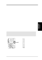
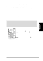
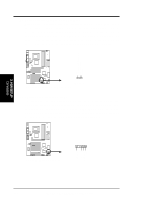
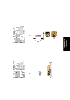
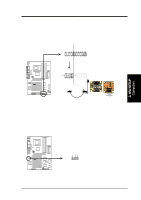
3. H/W SETUP Connectors 3. HARDWARE SETUP 11) Power Supply Connectors (20-pin block ATXPWR) This connector connects to an ATX 12V power supply. The plugs from the power supply fits in only one orientation because of the different hole sizes. Find the proper orientation and push down firmly making sure that the pins are aligned. IMPORTANT: Make sure that the ATX 12V power supply (minimum recommended wattage: 230W) can supply at least 10mA on the +5-volt standby lead (+5VSB). The system may become unstable and may experience difficulty powering up if the power supply is inadequate. For Wake-On-LAN support, the ATX power supply must supply at least 720mA +5VSB. CUV4X-E ® +3.3 Volts -12.0 Volts Ground Power Supply On Ground Ground Ground -5.0 Volts +5.0 Volts +5.0 Volts CUV4X-E ATX Power Connector +3.3 Volts +3.3 Volts Ground +5.0 Volts Ground +5.0 Volts Ground Power Good +5V Standby +12.0 Volts 12) Power Supply Thermal Sensor Connector (2-pin block JTPWR) The power supply thermal monitoring cable connects to this 2-pin connector. Make sure to connect the cable to use the thermal monitoring feature of the motherboard. CUV4X-E ® JTPWR Power Supply Thermal Sensor CUV4X-E Thermal Sensor Connector 40 ASUS CUV4X-E User's Manual
-
 1
1 -
2
-
3
-
4
-
5
-
6
-
7
-
8
-
9
-
10
-
11
-
12
-
13
-
14
-
15
-
16
-
17
-
18
-
19
-
20
-
21
-
22
-
23
-
24
-
25
-
26
-
27
-
28
-
29
-
30
-
31
-
32
-
33
-
34
-
 35
35 -
 36
36 -
 37
37 -
 38
38 -
 39
39 -
 40
40 -
 41
41 -
 42
42 -
 43
43 -
 44
44 -
 45
45 -
46
-
47
-
48
-
49
-
50
-
51
-
52
-
53
-
54
-
55
-
56
-
57
-
58
-
59
-
60
-
61
-
62
-
63
-
64
-
65
-
66
-
67
-
68
-
69
-
70
-
71
-
72
-
73
-
74
-
75
-
76
-
77
-
78
-
79
-
80
-
81
-
82
-
83
-
84
-
85
-
86
-
87
-
88
-
89
-
90
-
91
-
92
-
93
-
94
-
95
-
96
-
97
-
98
-
99
-
100
 |
 |
