Asus CUV4X-E CUV4X-E User Manual - Page 36
ASUS CUV4X-E User's Manual
 |
UPC - 610839878079
View all Asus CUV4X-E manuals
Add to My Manuals
Save this manual to your list of manuals |
Page 36 highlights
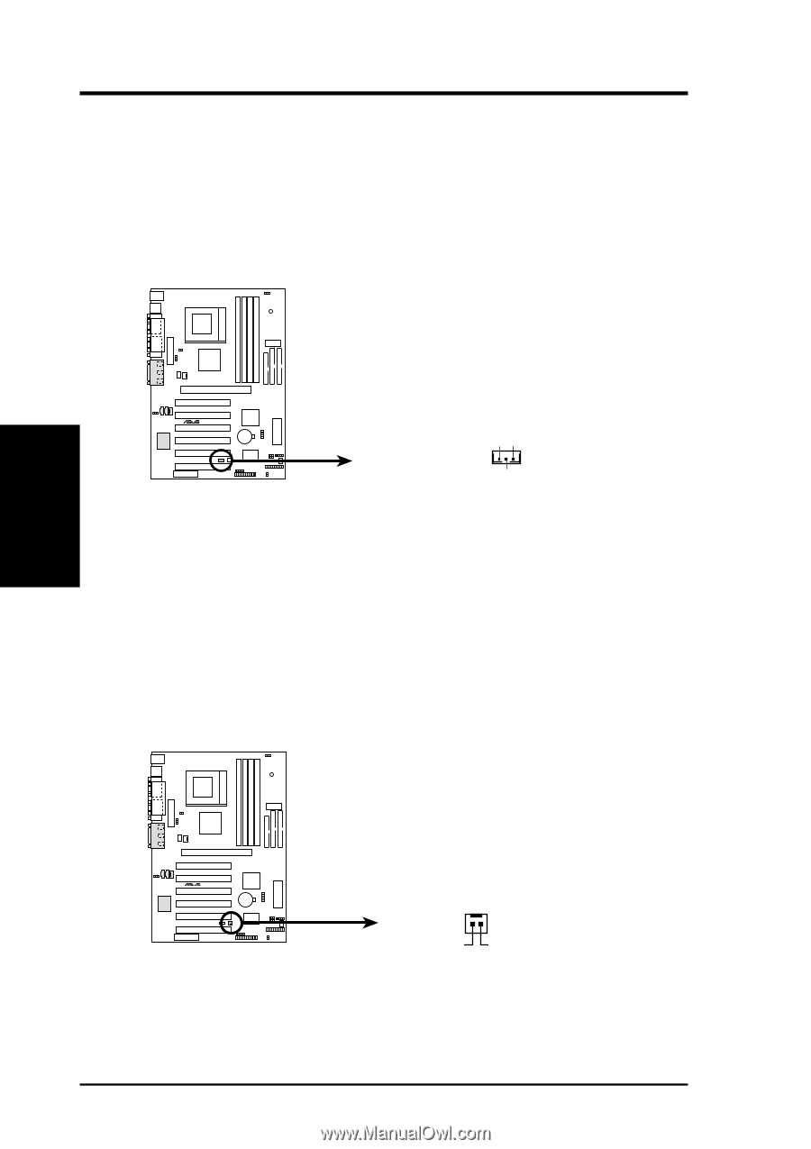
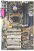
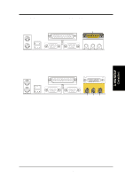
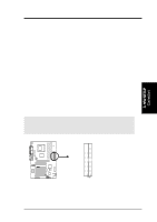
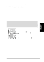
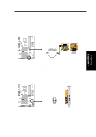
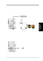
3. HARDWARE SETUP 4) Wake-On-LAN Connector (3-pin WOL_CON) This connector connects to a LAN card with a Wake-On-LAN output, such as the ASUS PCI-L101 Ethernet card (see 7. Appendix). The connector powers up the system when a wakeup packet or signal is received through the LAN card. IMPORTANT: This feature requires that the Wake-On-LAN or PCI Device parameter is enabled (see 4.5.1 Power Up Control) and that the system has an ATX power supply with at least 720mA +5V standby power. IMPORTANT: Requires an ATX power supply with at least 720mA +5 volt standby power. CUV4X-E ® WOL_CON +5 Volt Standby PME CUV4X-E Wake-On-LAN Connector Ground 5) Wake-On-Ring Connector (2-pin WOR) This connector connects to internal modem cards with a Wake-On-Ring output. The connector powers up the system when a ringup packet or signal is received through the internal modem card. NOTE: For external modems, Wake-On-Ring is detected through the COM port. IMPORTANT: This feature requires that the Power Up On External Modem Act parameter is enabled (see 4.5.1 Power Up Control) and that the system has an ATX power supply with at least 720mA +5V standby power. 3. H/W SETUP Connectors CUV4X-E ® WOR 1 2 Ground RI# CUV4X-E Wake-On-Ring Connector 36 ASUS CUV4X-E User's Manual
-
 1
1 -
2
-
3
-
4
-
5
-
6
-
7
-
8
-
9
-
10
-
11
-
12
-
13
-
14
-
15
-
16
-
17
-
18
-
19
-
20
-
21
-
22
-
23
-
24
-
25
-
26
-
27
-
28
-
29
-
30
-
 31
31 -
 32
32 -
 33
33 -
 34
34 -
 35
35 -
 36
36 -
 37
37 -
 38
38 -
 39
39 -
 40
40 -
 41
41 -
42
-
43
-
44
-
45
-
46
-
47
-
48
-
49
-
50
-
51
-
52
-
53
-
54
-
55
-
56
-
57
-
58
-
59
-
60
-
61
-
62
-
63
-
64
-
65
-
66
-
67
-
68
-
69
-
70
-
71
-
72
-
73
-
74
-
75
-
76
-
77
-
78
-
79
-
80
-
81
-
82
-
83
-
84
-
85
-
86
-
87
-
88
-
89
-
90
-
91
-
92
-
93
-
94
-
95
-
96
-
97
-
98
-
99
-
100
 |
 |