Asus MAXIMUS VIII EXTREME User Guide - Page 84
OC Panel II, 2.4.1 OC Panel II Overview
 |
View all Asus MAXIMUS VIII EXTREME manuals
Add to My Manuals
Save this manual to your list of manuals |
Page 84 highlights
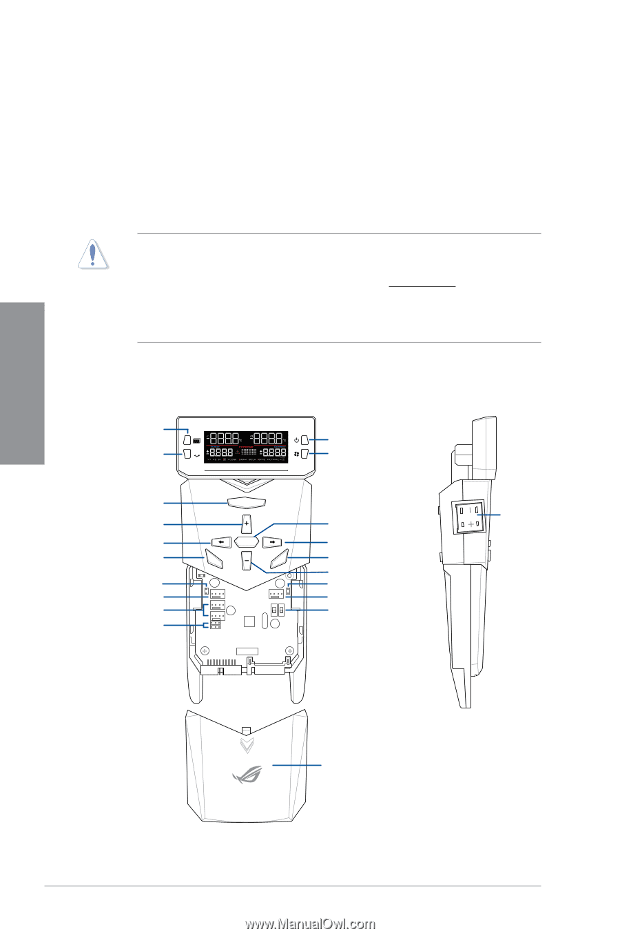
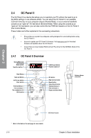
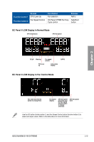
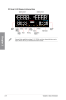
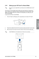
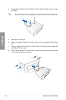
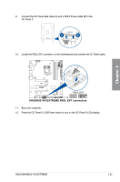
Chapter 2 2.4 OC Panel II The OC Panel II is a device that allows you to overclock your PC without the need to go to the BIOS settings or use software utilities. You can setup the OC Panel II in an available 5.25-inch drive bay on your computer chassis (Normal Mode), or as an external handheld console on an "open-air" OC test bench (Extreme Mode). When using the console as an "open-air" OC test bench, you can also control the two PWM fan headers on the OC Panel II (Fan Control Mode). These modes are further explained in the succeeding subsections. • Ensure that your system has adequate cooling designed for overclocking before using the OC Panel II. • Ensure to update your OC Panel II's firmware. Visit www.asus.com for the latest firmware and updates about the OC Panel II. • Ensure that you have installed ROG Connect Plus driver for the NORMAL Mode of the OC Panel II. 2.4.1 OC Panel II Overview Normal/Extreme/ Fan Control Mode switch Function button 1* OC LCM Power Button Function button 2* OC Start Button Value up Button Left Arrow button Clear button Thermal Sensor 1 Fan connector 1 Fan connectors 3,4 VGA hotwire Start OK Clear Reset ON ON OFF OFF OK button Right Arrow button Reset button Value Down button Thermal Sensor 2 Fan connector 2 Pause and Slow Mode Start Subzero Sense connector OK Clear Re OC Panel II cover * Refer to the table on the next page for more details. 2-18 Chapter 2: Basic Installation
-
 1
1 -
2
-
3
-
4
-
5
-
6
-
7
-
8
-
9
-
10
-
11
-
12
-
13
-
14
-
15
-
16
-
17
-
18
-
19
-
20
-
21
-
22
-
23
-
24
-
25
-
26
-
27
-
28
-
29
-
30
-
31
-
32
-
33
-
34
-
35
-
36
-
37
-
38
-
39
-
40
-
41
-
42
-
43
-
44
-
45
-
46
-
47
-
48
-
49
-
50
-
51
-
52
-
53
-
54
-
55
-
56
-
57
-
58
-
59
-
60
-
61
-
62
-
63
-
64
-
65
-
66
-
67
-
68
-
69
-
70
-
71
-
72
-
73
-
74
-
75
-
76
-
77
-
78
-
 79
79 -
 80
80 -
 81
81 -
 82
82 -
 83
83 -
 84
84 -
 85
85 -
 86
86 -
 87
87 -
 88
88 -
 89
89 -
90
-
91
-
92
-
93
-
94
-
95
-
96
-
97
-
98
-
99
-
100
-
101
-
102
-
103
-
104
-
105
-
106
-
107
-
108
-
109
-
110
-
111
-
112
-
113
-
114
-
115
-
116
-
117
-
118
-
119
-
120
-
121
-
122
-
123
-
124
-
125
-
126
-
127
-
128
-
129
-
130
-
131
-
132
-
133
-
134
-
135
-
136
-
137
-
138
-
139
-
140
-
141
-
142
-
143
-
144
-
145
-
146
-
147
-
148
-
149
-
150
-
151
-
152
-
153
-
154
-
155
-
156
-
157
-
158
-
159
-
160
-
161
-
162
-
163
-
164
-
165
-
166
-
167
-
168
-
169
-
170
-
171
-
172
-
173
-
174
-
175
-
176
-
177
-
178
-
179
-
180
-
181
-
182
-
183
-
184
-
185
-
186
-
187
-
188
-
189
-
190
-
191
-
192
-
193
-
194
-
195
-
196
-
197
-
198
-
199
-
200
-
201
-
202
-
203
-
204
-
205
-
206
-
207
-
208
-
209
-
210
-
211
-
212
-
213
-
214
-
215
-
216
-
217
-
218
-
219
-
220
-
221
-
222
-
223
-
224
-
225
-
226
 |
 |