Asus P2L-N P2L-N User Manual - Page 13
ASUS P2L-N/P2E-N User's Manual, Jumpers, Expansion Slots, Hardwar, e Monitor, Connectors - game
 |
View all Asus P2L-N manuals
Add to My Manuals
Save this manual to your list of manuals |
Page 13 highlights
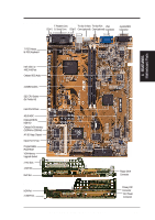
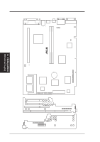
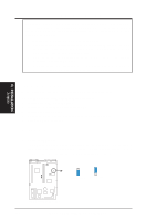
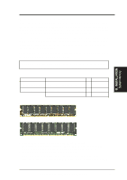
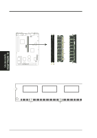
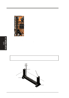
III. INSTALLATION Map of Board Jumpers 1) JP1 III. INSTALLATION p. 13 Audio Setting (Enable/Disable) Expansion Slots 1) DIMM Sockets 2) SEC CPU Slot 3) SLOT 1* 4) PCI 1, 2 p. 15 168-Pin DIMM Memory Expansion Sockets p. 17 Single Edge Contact CPU Support p. 22 16-bit ISA Bus Expansion Slots* p. 22 32-bit PCI Bus Expansion Slots Hardware Monitor 1) RT4 p. 20 Pentium II Processor Thermal Sensor Connector Connectors 1) PS2KBMS p. 24 PS/2 Keyboard Connector (6-pin Female) 2) PS2KBMS p. 24 PS/2 Mouse Connector (6-pin Female) 3) GAME p. 24 Joystick or MIDI Connector (15-pin Female) 4) PRINTER p. 25 Parallel (Printer) Port Connector (25-pin Female) 5) COM1, COM2 p. 25 Serial Port COM1 and COM2 (Two 9-pin Male) 6) VGA p. 25 VGA Compatible Connector (15-pin Female) 7) COM-OUT (optional) p. 25 Television Connector (RCA & 4-pin Female S-Video) 8) USB p. 26 Universal Serial BUS Ports 1 & 2 (Two 4-pin Female) 9) IR p. 26 Infrared Module 10) POWER p. 26 NLX Motherboard Power Connector (20-pin Block) 11) IDE1 p. 27 Primary IDE Connector (40-pin Block) 12) FLOPPY p. 27 Floppy Drive Connector (34-pin Block) 13. LAN_LED, WOL_ p. 27 LAN Activity Connectors (2-pin & 3-pin) 14) PAN_CON p. 28 Front Panel Display LEDs and Switches (16-1 pin) 15) MIC_CON p. 28 Front Panel Microphone Jack Connector (2 pin) 16) AMC p. 30 ATI Multimedia Connector (40-3 pin Block) 17) AUDIO p. 30 Back Panel Audio Connectors (10-1 pin Block) 18) CPU_FAN p. 30 CPU Fan Power (3-pin Block) 19) VGA Memory p. 31 Onboard VGA Memory Expansion Sockets (40 pins) 20) CDROM p. 31 CD-ROM Drive Connector (50-1 pins) *The onboard hardware monitor uses the address 290H-297H so legacy ISA cards must not use this address or else conflicts will occur. ASUS P2L-N/P2E-N User's Manual 13
-
 1
1 -
2
-
3
-
4
-
5
-
6
-
7
-
 8
8 -
 9
9 -
 10
10 -
 11
11 -
 12
12 -
 13
13 -
 14
14 -
 15
15 -
 16
16 -
 17
17 -
 18
18 -
19
-
20
-
21
-
22
-
23
-
24
-
25
-
26
-
27
-
28
-
29
-
30
-
31
-
32
-
33
-
34
-
35
-
36
-
37
-
38
-
39
-
40
-
41
-
42
-
43
-
44
-
45
-
46
-
47
-
48
-
49
-
50
-
51
-
52
-
53
-
54
-
55
-
56
-
57
-
58
-
59
-
60
-
61
-
62
-
63
-
64
-
65
-
66
-
67
-
68
-
69
-
70
-
71
-
72
-
73
-
74
-
75
-
76
-
77
-
78
-
79
-
80
-
81
-
82
-
83
-
84
-
85
-
86
-
87
-
88
-
89
-
90
-
91
-
92
-
93
-
94
-
95
-
96
-
97
-
98
-
99
-
100
-
101
-
102
-
103
-
104
-
105
-
106
-
107
-
108
-
109
-
110
-
111
-
112
-
113
-
114
-
115
-
116
-
117
-
118
-
119
-
120
 |
 |