Asus P2L-N P2L-N User Manual - Page 29
Front Panel Descriptions - notebook
 |
View all Asus P2L-N manuals
Add to My Manuals
Save this manual to your list of manuals |
Page 29 highlights
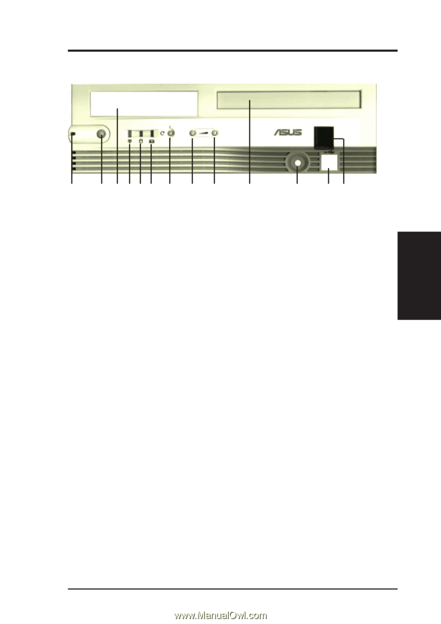
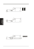
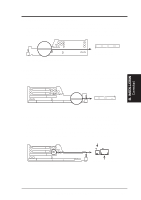
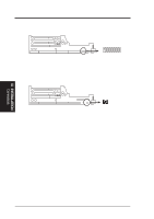
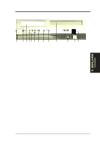
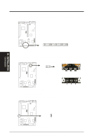
III. INSTALLATION Front Panel Descriptions III. INSTALLATION Connectors A B C DEF G H I J K LM A. System Power LED Lights when the system is powered on and blinks when it is in sleep mode. B. NLX Power Button/ Soft Power Button Switches between ON, OFF, and SLEEP mode. The functions are controlled and configurable through the "Power Up Control" in the POWER MANAGEMENT SETUP of the BIOS SOFTWARE. C. Floppy Drive Bay Accepts a standard 3.5inch floppy drive, LS-120, or other compatible devices. D. Network Activity LED Blinks when data is transfered to or from a network card. (The network card requires an external LED wire connected to the Riser card's LAN_LED.) E. IDE Activity LED Blinks when data is transfered via the IDE channels, includes the CD-ROM. F. Message LED The LED will remain lit when there is no modem activity and blink when there is data being transfered or waiting in the inbox. Requires ACPI OS support. G. Reset Button Switch used for rebooting the computer without having to use the power switch H. Volume Down Button Decreases the onboard audio amplifier's volume. I. Volume Up Button Increases the onboard audio amplifier's volume. J. CD-ROM Drive Bay Accepts only a notebook-size CD-ROM. K. Microphone Jack Accepts a 1/8inch connector from a microphone or other audio source. L. USB Port1 and Port2 Accepts 15 USB devices on each port. M. Infrared Window Allows transmission and reception of infrared signals by the onboard module. ASUS P2L-N/P2E-N User's Manual 29
-
 1
1 -
2
-
3
-
4
-
5
-
6
-
7
-
8
-
9
-
10
-
11
-
12
-
13
-
14
-
15
-
16
-
17
-
18
-
19
-
20
-
21
-
22
-
23
-
 24
24 -
 25
25 -
 26
26 -
 27
27 -
 28
28 -
 29
29 -
 30
30 -
 31
31 -
 32
32 -
 33
33 -
 34
34 -
35
-
36
-
37
-
38
-
39
-
40
-
41
-
42
-
43
-
44
-
45
-
46
-
47
-
48
-
49
-
50
-
51
-
52
-
53
-
54
-
55
-
56
-
57
-
58
-
59
-
60
-
61
-
62
-
63
-
64
-
65
-
66
-
67
-
68
-
69
-
70
-
71
-
72
-
73
-
74
-
75
-
76
-
77
-
78
-
79
-
80
-
81
-
82
-
83
-
84
-
85
-
86
-
87
-
88
-
89
-
90
-
91
-
92
-
93
-
94
-
95
-
96
-
97
-
98
-
99
-
100
-
101
-
102
-
103
-
104
-
105
-
106
-
107
-
108
-
109
-
110
-
111
-
112
-
113
-
114
-
115
-
116
-
117
-
118
-
119
-
120
 |
 |