Asus P2L-N P2L-N User Manual - Page 27
Installation
 |
View all Asus P2L-N manuals
Add to My Manuals
Save this manual to your list of manuals |
Page 27 highlights
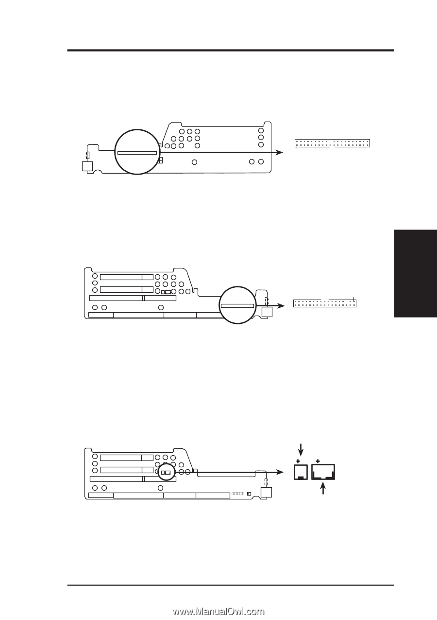
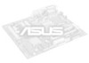
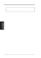
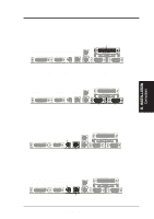
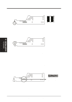
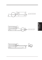
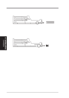
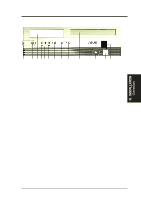
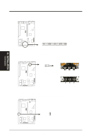
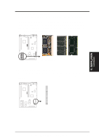
III. INSTALLATION Connectors III. INSTALLATION 11. Primary IDE Connector (40-1 pin IDE) This connector supports the provided IDE hard disk drive ribbon cable. After connecting one end to the riser card, connect the other end to a hard disk drive. The primary IDE channel supports both a master and a slave IDE device but the system housing size only permits a standard IDE hard drive to be installed. IDE (Hard Disk Drive) Connector Primary IDE Connector Pin 1 Orient the red stripe on the IDE ribbon cable to Pin 1 12. 3.5inch Floppy Disk Drive Connector (34-1 pin FLOPPY) This connector supports the provided floppy drive ribbon cable. After connecting the single end to the riser card, connect the other end to a 3.5inch floppy disk drive. Riser Card Front Floppy Disk Drive Connector Floppy Drive Conn. Riser Slot Panel Conn. Pin 1 Orient the red stripe on the floppy ribbon cable to Pin 1 13. LAN Activity Connectors (2 pin LAN_LED & 3 pin WOL_CON) These connectors support Local Area Network (LAN) cards such as the ASUS PCI-L101 with output signals for data transfer activity. The LAN_LED connector allows the front panel LED to blink during transfer activity between the network and the computer. The WOL_CON connector allows the system to power up when there is a wakeup package (signal) received from the network. LAN activity LED Riser Card Front LAN Activity Connectors Riser Slot Wake on LAN activity ASUS P2L-N/P2E-N User's Manual 27
-
 1
1 -
2
-
3
-
4
-
5
-
6
-
7
-
8
-
9
-
10
-
11
-
12
-
13
-
14
-
15
-
16
-
17
-
18
-
19
-
20
-
21
-
 22
22 -
 23
23 -
 24
24 -
 25
25 -
 26
26 -
 27
27 -
 28
28 -
 29
29 -
 30
30 -
 31
31 -
 32
32 -
33
-
34
-
35
-
36
-
37
-
38
-
39
-
40
-
41
-
42
-
43
-
44
-
45
-
46
-
47
-
48
-
49
-
50
-
51
-
52
-
53
-
54
-
55
-
56
-
57
-
58
-
59
-
60
-
61
-
62
-
63
-
64
-
65
-
66
-
67
-
68
-
69
-
70
-
71
-
72
-
73
-
74
-
75
-
76
-
77
-
78
-
79
-
80
-
81
-
82
-
83
-
84
-
85
-
86
-
87
-
88
-
89
-
90
-
91
-
92
-
93
-
94
-
95
-
96
-
97
-
98
-
99
-
100
-
101
-
102
-
103
-
104
-
105
-
106
-
107
-
108
-
109
-
110
-
111
-
112
-
113
-
114
-
115
-
116
-
117
-
118
-
119
-
120
 |
 |