Asus P3C-LS P3C-LS User Manual - Page 14
Hardware Setup
 |
View all Asus P3C-LS manuals
Add to My Manuals
Save this manual to your list of manuals |
Page 14 highlights
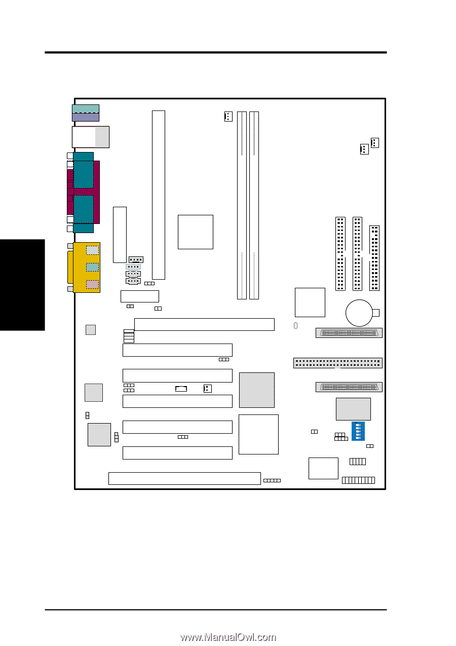
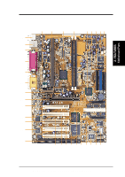
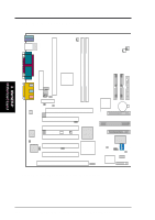
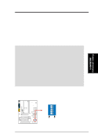
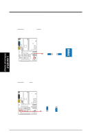
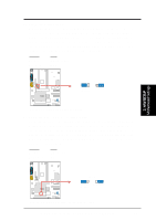
12345 O N 3. H/W SETUP Motherboard Layout 3. HARDWARE SETUP 3.1 Motherboard Layout T: Mouse PS2KBMS B: Keyboard OPTIONAL (RJ-45 only) Bottom: USB1 USB2 Top: RJ-45 COM1 CPU_FAN CHA_FAN PWR_FAN RIMM1 (16/18 bit, 184-pin module) RIMM0 (16/18 bit, 184-pin module) CPU1 (Slot 1) PARALLEL PORT OPTIONAL ATX Power Connector GAME_AUDIO SECONDARY IDE PRIMARY IDE FLOPPY COM2 Line Out MODEM Intel 820 Memory Controller Hub (MCH) Line In VIDEO AUX Mic CD_IN In JP10 Audio Modem Riser 1 2 RIMM0 RIMM1 3 4 SPDIFIN TRCPU Row Accelerated Graphics Port (AGP Pro) JP4 Audio Codec JP5 JP6 JP7 P3C-LS / L / S PCI Slot 1 (PCI1) JP17 Intel JP8 82559 JP9 10/100 LAN SPDIOOUT PCI Slot 2 (PCI2) Adaptec WOL_CON JP15 (WOR) 7892B Ultra160 SCSI PCI Slot 3 (PCI3) Controller Intel I/O Controller Hub (ICH) CR2032 3V Lithium Cell CMOS Power CLRTC 35 68 1 34 68-Pin Ultra160 SCSI Connector 1 50-Pin Ultra-Fast SCSI Connector 35 68 1 34 68-Pin UltraWide SCSI Connector Adaptec 3860Q Chipset 32-bit PCI Audio Chipset JP2 PCI Slot 4 (PCI4) JP12 PCI Slot 5 (PCI5) ISA Slot (SLOT2) PCI-to-ISA Bridge JP18 (SMB) TRPWR JP22 DIP Switches CHASSIS ASUS ASIC with Hardware Monitor IDELED IR PANEL Grayed midboard items are optional at the time of purchase. 14 ASUS P3C-L / P3C-S / P3C-LS User's Manual
-
 1
1 -
2
-
3
-
4
-
5
-
6
-
7
-
8
-
 9
9 -
 10
10 -
 11
11 -
 12
12 -
 13
13 -
 14
14 -
 15
15 -
 16
16 -
 17
17 -
 18
18 -
 19
19 -
20
-
21
-
22
-
23
-
24
-
25
-
26
-
27
-
28
-
29
-
30
-
31
-
32
-
33
-
34
-
35
-
36
-
37
-
38
-
39
-
40
-
41
-
42
-
43
-
44
-
45
-
46
-
47
-
48
-
49
-
50
-
51
-
52
-
53
-
54
-
55
-
56
-
57
-
58
-
59
-
60
-
61
-
62
-
63
-
64
-
65
-
66
-
67
-
68
-
69
-
70
-
71
-
72
-
73
-
74
-
75
-
76
-
77
-
78
-
79
-
80
-
81
-
82
-
83
-
84
-
85
-
86
-
87
-
88
-
89
-
90
-
91
-
92
-
93
-
94
-
95
-
96
-
97
-
98
-
99
-
100
-
101
-
102
-
103
-
104
-
105
-
106
-
107
-
108
-
109
-
110
-
111
-
112
-
113
-
114
 |
 |