Asus P3C-LS P3C-LS User Manual - Page 44
Joystick/MIDI Connector Gold 15-pin GAME_AUDIO optional
 |
View all Asus P3C-LS manuals
Add to My Manuals
Save this manual to your list of manuals |
Page 44 highlights
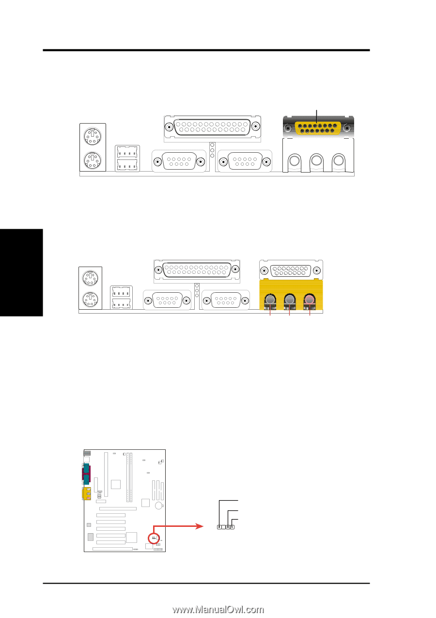
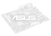
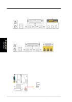
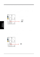
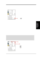
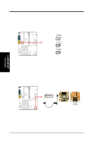
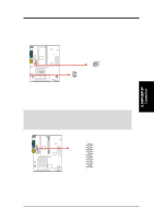
3. HARDWARE SETUP 7) Joystick/MIDI Connector (Gold 15-pin GAME_AUDIO) (optional) You may connect game joysticks or game pads to this connector for playing games. Connect MIDI devices for playing or editing professional audio. Joystick/Midi (15-pin Female) 3. H/W SETUP Connectors 8) Audio Port Connectors (Three 1/8" GAME_AUDIO) (optional) Line Out (lime) can be connected to headphones or preferably powered speakers. Line In (light blue) allows tape players or other audio sources to be recorded by your computer or played through the Line Out (lime). Mic (pink) allows microphones to be connected for inputting voice. Line Out Line In Mic 1/8" Stereo Audio Connectors 9) Chassis Intrusion Lead (2-pin CHASSIS) This lead is for a chassis designed for chassis intrusion detection. After-market toggle switches may also be installed to the chassis panel or on any removable components. Two wires should be available from the chassis to connect to this lead. When any chassis component is removed, the circuit should open and the motherboard will record a chassis intrusion event. The event can then be processed by software such as LDCM. If the chassis intrusion lead is not used, a jumper cap must be placed over the pins to close the circuit. PARALLEL PORT OPTIONAL P3C-LS / L / S 1 2 3 4 +5Volt (Power Supply Stand By) Chassis Signal 1 Ground CHASSIS P3C-LS/L/S Chassis Open Alarm Lead 44 ASUS P3C-L / P3C-S / P3C-LS User's Manual
-
 1
1 -
2
-
3
-
4
-
5
-
6
-
7
-
8
-
9
-
10
-
11
-
12
-
13
-
14
-
15
-
16
-
17
-
18
-
19
-
20
-
21
-
22
-
23
-
24
-
25
-
26
-
27
-
28
-
29
-
30
-
31
-
32
-
33
-
34
-
35
-
36
-
37
-
38
-
 39
39 -
 40
40 -
 41
41 -
 42
42 -
 43
43 -
 44
44 -
 45
45 -
 46
46 -
 47
47 -
 48
48 -
 49
49 -
50
-
51
-
52
-
53
-
54
-
55
-
56
-
57
-
58
-
59
-
60
-
61
-
62
-
63
-
64
-
65
-
66
-
67
-
68
-
69
-
70
-
71
-
72
-
73
-
74
-
75
-
76
-
77
-
78
-
79
-
80
-
81
-
82
-
83
-
84
-
85
-
86
-
87
-
88
-
89
-
90
-
91
-
92
-
93
-
94
-
95
-
96
-
97
-
98
-
99
-
100
-
101
-
102
-
103
-
104
-
105
-
106
-
107
-
108
-
109
-
110
-
111
-
112
-
113
-
114
 |
 |