Asus P3C-LS P3C-LS User Manual - Page 28
ASUS P3C-L / P3C-S / P3C-LS User's Manual, Removing Memory from the Riser
 |
View all Asus P3C-LS manuals
Add to My Manuals
Save this manual to your list of manuals |
Page 28 highlights
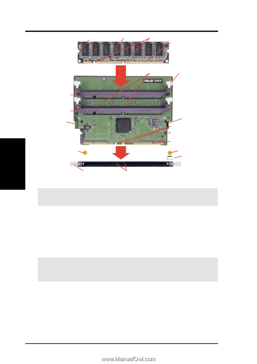
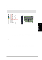
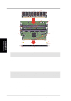
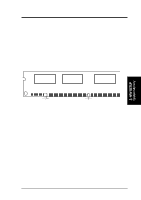
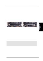
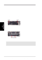
3. H/W SETUP System Memory 3. HARDWARE SETUP MOUNTING NOTCH SDRAM NOTCH KEYS CONNECTORS RIBS (inside socket) EJECTOR J1M1 J1M2 CAPTIVE NUT (back of riser) Screw to secure riser to case ATTACH MOUNT BRIDGE (top view) Screw to secure riser to case CAPTIVE NUT (back of riser) NOTCH KEYS MOUNTING NOTCH CONNECTORS ATTACH MOUNT BRIDGE (top view) CPU FAN EJECTOR RIBS (inside socket) RIMM0 (top view) 4. Screw the captive nuts into the attach mount bridges. WARNING! Do not overtighten the captive nut. Doing so could damage your motherboard. Tighten captive nuts to no more than 6±1inch/pound. 5. With the ejectors of the DIMM socket (J1M1/J1M2) in the open position and while holding the riser along its edges, push down gently but firmly on one side of the memory module until it snaps into place and then do the same on the other side. The guides on the socket's ejectors should go through the two mounting notches on the module and the ejectors should close. If necessary, push the ejectors inward to secure the module in place. IMPORTANT: When populating both DIMM sockets, the module density on J1M2 must be greater than the one on J1M1. For example, if you are installing a 64MB memory on J1M1, you must install memory greater than or equal to 64MB on J1M2. Removing Memory from the Riser 1. Unscrew the captive nuts from the attach mount bridge. 2. Push both ejectors (J1M1/J1M2) outward while holding the module along its side edges. Pull the module straight up and out of the DIMM sockets on the riser. 28 ASUS P3C-L / P3C-S / P3C-LS User's Manual
-
 1
1 -
2
-
3
-
4
-
5
-
6
-
7
-
8
-
9
-
10
-
11
-
12
-
13
-
14
-
15
-
16
-
17
-
18
-
19
-
20
-
21
-
22
-
 23
23 -
 24
24 -
 25
25 -
 26
26 -
 27
27 -
 28
28 -
 29
29 -
 30
30 -
 31
31 -
 32
32 -
 33
33 -
34
-
35
-
36
-
37
-
38
-
39
-
40
-
41
-
42
-
43
-
44
-
45
-
46
-
47
-
48
-
49
-
50
-
51
-
52
-
53
-
54
-
55
-
56
-
57
-
58
-
59
-
60
-
61
-
62
-
63
-
64
-
65
-
66
-
67
-
68
-
69
-
70
-
71
-
72
-
73
-
74
-
75
-
76
-
77
-
78
-
79
-
80
-
81
-
82
-
83
-
84
-
85
-
86
-
87
-
88
-
89
-
90
-
91
-
92
-
93
-
94
-
95
-
96
-
97
-
98
-
99
-
100
-
101
-
102
-
103
-
104
-
105
-
106
-
107
-
108
-
109
-
110
-
111
-
112
-
113
-
114
 |
 |