Asus P3C-LS P3C-LS User Manual - Page 24
System Memory
 |
View all Asus P3C-LS manuals
Add to My Manuals
Save this manual to your list of manuals |
Page 24 highlights
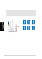
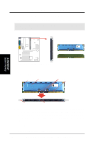
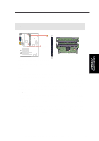
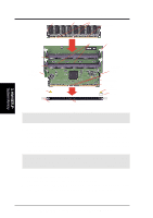
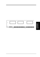
3. H/W SETUP System Memory 3. HARDWARE SETUP 3.5 System Memory NOTE: No hardware or BIOS setup is required after adding or removing memory. This motherboard has two Rambus Inline Memory Module (RIMM) sockets. These sockets (see Important notes for details) support Direct RDRAMs (both ECC and non-ECC are supported) in 64, 96, 128, 192, 256, and 512MB densities for a maximum of 1GB. With the optional ASUS DR2 DIMM Riser, unbuffered Synchronous Dynamic Random Access Memory (SDRAM, 3.3V power level) in 64, 128, 256, or 512MB densities with Serial Presence Detect (SPD) can also be used on the second socket for a maximum of 1GB. The chipset's Error Checking and Correction (ECC) feature is available only when using RDRAMs. ECC feature is not available when using SDRAM with an ASUS DIMM Riser (ECC memory modules may still be used, but the ECC function will not be available). For memory speed setup, see 4.4.1 CHIP Configuration. IMPORTANT General 1. DO NOT attempt to mix RDRAMs with an SDRAM+Riser or vice versa. RDRAM 1. If more than one socket will be populated with RDRAMs, RIMM0 must be populated first and then RIMM1. If only one socket will be populated, RIMM0 must be populated with RDRAM, RIMM1 with C-RIMM. See table for an overview. SDRAM 1. To use SDRAM with this motherboard, an ASUS DR2 DIMM Riser must be installed as an interface (see 3.5.2 Installing Memory Using the ASUS DR2 DIMM Riser). The riser must (and can only) be inserted into RIMM0, with the bundled C-RIMM inserted into RIMM1. See table for an overview. 2. When populating both DIMM sockets in the riser, the module density on J1M2 must be greater than the one on J1M1. 3. This motherboard's chipset only supports 64Mbit and 128Mbit SDRAMs (see SDRAM Configurations). 32Mx4 128 Mbit support is for registered DIMMs only. 4Mx16 64 Mbit support is for unbufferred DIMMs only. C-RIMM/CTRIMM 1. Depending on your configuration, a C-RIMM (Continuity RIMM) must be used to complete the sockets that are not populated by either RDRAMs or an ASUS DIMM Riser (when using SDRAM). C-RIMM is necessary to avoid breaking the signal lines, which are a serial connection in a Rambus interface, such as used in this motherboard. The C-RIMM assures the electrical integrity of a Rambus interface. 24 ASUS P3C-L / P3C-S / P3C-LS User's Manual
-
 1
1 -
2
-
3
-
4
-
5
-
6
-
7
-
8
-
9
-
10
-
11
-
12
-
13
-
14
-
15
-
16
-
17
-
18
-
 19
19 -
 20
20 -
 21
21 -
 22
22 -
 23
23 -
 24
24 -
 25
25 -
 26
26 -
 27
27 -
 28
28 -
 29
29 -
30
-
31
-
32
-
33
-
34
-
35
-
36
-
37
-
38
-
39
-
40
-
41
-
42
-
43
-
44
-
45
-
46
-
47
-
48
-
49
-
50
-
51
-
52
-
53
-
54
-
55
-
56
-
57
-
58
-
59
-
60
-
61
-
62
-
63
-
64
-
65
-
66
-
67
-
68
-
69
-
70
-
71
-
72
-
73
-
74
-
75
-
76
-
77
-
78
-
79
-
80
-
81
-
82
-
83
-
84
-
85
-
86
-
87
-
88
-
89
-
90
-
91
-
92
-
93
-
94
-
95
-
96
-
97
-
98
-
99
-
100
-
101
-
102
-
103
-
104
-
105
-
106
-
107
-
108
-
109
-
110
-
111
-
112
-
113
-
114
 |
 |