Asus P3C-LS P3C-LS User Manual - Page 49
ASUS P3C-L / P3C-S / P3C-LS User's Manual, Digital Audio Interface Header 2-pin SPDIFIN/SPDIOOUT,
 |
View all Asus P3C-LS manuals
Add to My Manuals
Save this manual to your list of manuals |
Page 49 highlights
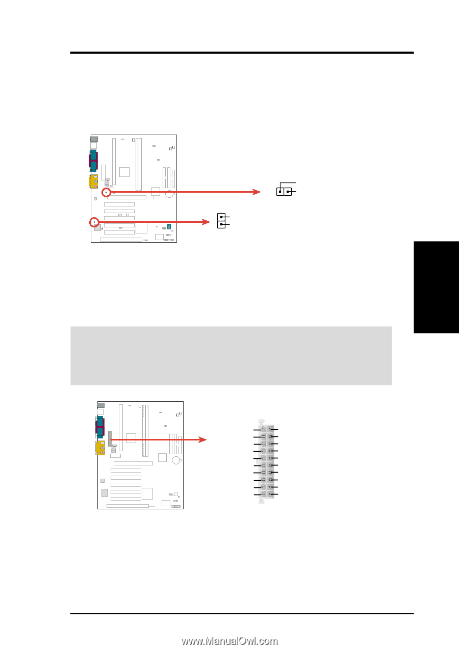
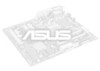
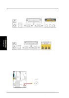
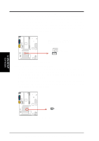
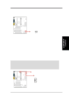
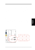
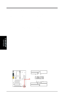
3. H/W SETUP Connectors 3. HARDWARE SETUP 18) Digital Audio Interface Header (2-pin SPDIFIN/SPDIOOUT) only with Yamaha PCI audio This header is the digital link between the motherboard and your devices, such as CD player, sampler, or DAT recorder. It allows the digital transmission of audio data in SPDIF (Sony/Philips Digital Interface) format. P3C-LS / L / S SPDI Signal Ground SPDIFIN Ground SPDO Signal SPDIOOUT P3C-LS/L/S Audio Digital Interface Connectors 19) ATX Power Supply Connector (20-pin block ATXPWR) This connector connects to an ATX power supply. The plug from the power supply will only insert in one orientation because of the different hole sizes. Find the proper orientation and push down firmly making sure that the pins are aligned. IMPORTANT: Make sure that your ATX power supply can supply at least 10mA on the +5-volt standby lead (+5VSB). You may experience difficulty in powering ON your system if your power supply cannot support the load. For WakeOn-LAN support, your ATX power supply must supply at least 720mA +5VSB. ATXPWR PARALLEL PORT OPTIONAL P3C-LS / L / S 1 2 3 4 +3.3 Volts -12.0 Volts Ground Power Supply On Ground Ground Ground -5.0 Volts +5.0 Volts +5.0 Volts P3C-LS/L/S ATX Power Connector +3.3 Volts +3.3 Volts Ground +5.0 Volts Ground +5.0 Volts Ground Power Good +5V Standby +12.0 Volts ASUS P3C-L / P3C-S / P3C-LS User's Manual 49
-
 1
1 -
2
-
3
-
4
-
5
-
6
-
7
-
8
-
9
-
10
-
11
-
12
-
13
-
14
-
15
-
16
-
17
-
18
-
19
-
20
-
21
-
22
-
23
-
24
-
25
-
26
-
27
-
28
-
29
-
30
-
31
-
32
-
33
-
34
-
35
-
36
-
37
-
38
-
39
-
40
-
41
-
42
-
43
-
 44
44 -
 45
45 -
 46
46 -
 47
47 -
 48
48 -
 49
49 -
 50
50 -
 51
51 -
 52
52 -
 53
53 -
 54
54 -
55
-
56
-
57
-
58
-
59
-
60
-
61
-
62
-
63
-
64
-
65
-
66
-
67
-
68
-
69
-
70
-
71
-
72
-
73
-
74
-
75
-
76
-
77
-
78
-
79
-
80
-
81
-
82
-
83
-
84
-
85
-
86
-
87
-
88
-
89
-
90
-
91
-
92
-
93
-
94
-
95
-
96
-
97
-
98
-
99
-
100
-
101
-
102
-
103
-
104
-
105
-
106
-
107
-
108
-
109
-
110
-
111
-
112
-
113
-
114
 |
 |