Asus P4-P5G41 User Manual - Page 16
Internal components
 |
View all Asus P4-P5G41 manuals
Add to My Manuals
Save this manual to your list of manuals |
Page 16 highlights
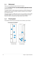
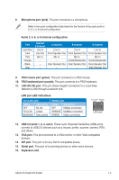
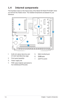
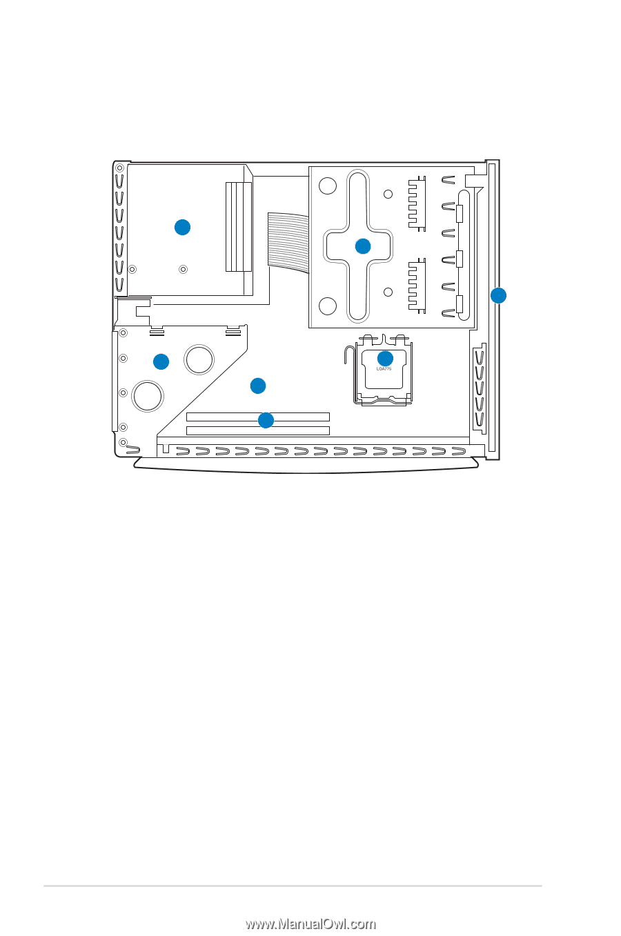
1.4 Internal components The illustration below is the internal view of the ASUS P2-P5G41/P4-P5G41 when you remove the chassis cover. The installed components are labeled for your reference. 3 1 2 4 7 5 6 1. 5.25 inch optical disk drive and 3.5 inch hard disk drive cage 2. Front panel assembly 3. Power supply unit 4. PCIE raiser bracket (connected to the motherboard PCIe slot) 5. ASUS motherboard 6. DIMM slots 7. LGA775 socket 1-6 Chapter 1: System introduction
-
 1
1 -
2
-
3
-
4
-
5
-
6
-
7
-
8
-
9
-
10
-
 11
11 -
 12
12 -
 13
13 -
 14
14 -
 15
15 -
 16
16 -
 17
17 -
 18
18 -
 19
19 -
 20
20 -
 21
21 -
22
-
23
-
24
-
25
-
26
-
27
-
28
-
29
-
30
-
31
-
32
-
33
-
34
-
35
-
36
-
37
-
38
-
39
-
40
-
41
-
42
-
43
-
44
-
45
-
46
-
47
-
48
-
49
-
50
-
51
-
52
-
53
-
54
-
55
-
56
-
57
-
58
-
59
-
60
-
61
-
62
-
63
-
64
-
65
-
66
-
67
-
68
-
69
-
70
-
71
-
72
-
73
-
74
-
75
 |
 |
1-6
Chapter 1: System introduction
1.4
Internal components
The illustration below is the internal view of the ASUS P2-P5G41/P4-P5G41 when
you remove the chassis cover. The installed components are labeled for your
reference.
1.
5.25 inch optical disk drive and
3.5 inch hard disk drive cage
2.
Front panel assembly
3.
Power supply unit
4.
PCIE raiser bracket (connected to
the motherboard PCIe slot)
5.
ASUS motherboard
6.
DIMM slots
7.
LGA775 socket
1
2
3
4
5
6
7