Asus P4-P5G41 User Manual - Page 38
P5Q8L Digital Audio Connectors
 |
View all Asus P4-P5G41 manuals
Add to My Manuals
Save this manual to your list of manuals |
Page 38 highlights
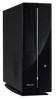
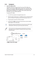
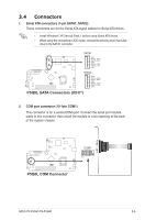
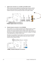
7. Digital audio connectors (4-1 pin SPDIF_OUT, SPDIF_OUT1) These connectors are for additional Sony/Philips Digital Interface (S/PDIF) ports. Connect the S/PDIF Out module cables to these connectors, then install the modules to slots opening at the back of the system chassis. +5V SPDIFOUT GND +5V SPDIFOUT GND P5Q8L SPDIF_OUT SPDIF_OUT1 P5Q8L Digital Audio Connectors 8. Chassis intrusion connector (4-1 pin CHASSIS) This connector is for a chassis-mounted intrusion detection sensor or switch. Connect one end of the chassis intrusion sensor or switch cable to this connector. The chassis intrusion sensor or switch sends a high-level signal to this connector when a chassis component is removed or replaced. The signal is then generated as a chassis intrusion event. By default, the pin labeled "Chassis Signal" and "Ground" are shorted with a jumper cap. Remove the jumper caps only when you intend to use the chassis intrusion detection feature. CHASSIS +5VSB_MB Chassis Signal GND P5Q8L P5Q8L Chassis Intrusion Connector 3-8 Chapter 3: Motherboard info
-
 1
1 -
2
-
3
-
4
-
5
-
6
-
7
-
8
-
9
-
10
-
11
-
12
-
13
-
14
-
15
-
16
-
17
-
18
-
19
-
20
-
21
-
22
-
23
-
24
-
25
-
26
-
27
-
28
-
29
-
30
-
31
-
32
-
 33
33 -
 34
34 -
 35
35 -
 36
36 -
 37
37 -
 38
38 -
 39
39 -
 40
40 -
 41
41 -
 42
42 -
 43
43 -
44
-
45
-
46
-
47
-
48
-
49
-
50
-
51
-
52
-
53
-
54
-
55
-
56
-
57
-
58
-
59
-
60
-
61
-
62
-
63
-
64
-
65
-
66
-
67
-
68
-
69
-
70
-
71
-
72
-
73
-
74
-
75
 |
 |