Asus P4-P5G41 User Manual - Page 32
Introduction, Motherboard layout - barebone
 |
View all Asus P4-P5G41 manuals
Add to My Manuals
Save this manual to your list of manuals |
Page 32 highlights
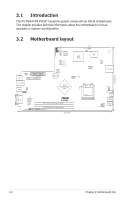
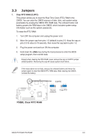
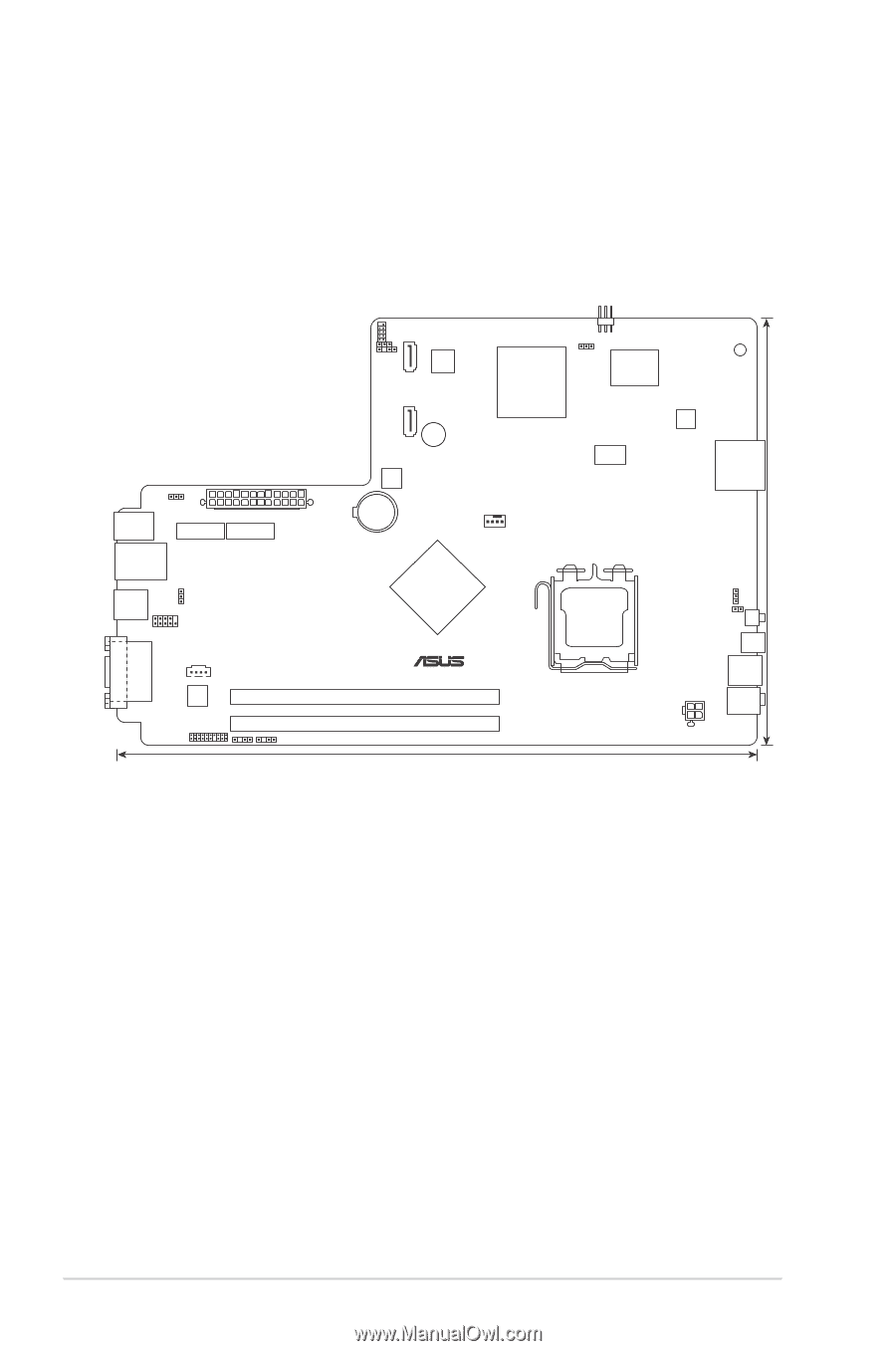
3.1 Introduction The P2-P5G41/P4-P5G41 barebone system comes with an ASUS motherboard. This chapter provides technical information about the motherboard for future upgrades or system reconfiguration. 3.2 Motherboard layout DEBUGPORT CLRTC SATA1 eNOVA MX-128 CHASSIS SATA2 BUZZER KBMS KBPWR PCIEX1_1 EATXPWR PCIEX1_2 LAN1_USB12 USB34 USBPW1-4 COM1 8Mb BIOS Lithium Cell CMOS Power Intel® EAGLELAKE G41 CD ALC 1200 AUDIO P5Q8L DDR2 DIMM_A1 (64bit, 240-pin module) DDR2 DIMM_B1 (64bit, 240-pin module) SPDIF_OUT SPDIF_OUT1 33cm(13in) Intel® ICH7 LED_CON PWR_FAN Super I/O RTM 870T-954 VIA VT6325 CR_SOCKET CPU_FAN LGA775 ATX12V USBPW56 RSTSW PWRSW E1394 USB56 FRONT_ AUD VGA DVI 22.4cm(8.8in) 3-2 Chapter 3: Motherboard info
-
 1
1 -
2
-
3
-
4
-
5
-
6
-
7
-
8
-
9
-
10
-
11
-
12
-
13
-
14
-
15
-
16
-
17
-
18
-
19
-
20
-
21
-
22
-
23
-
24
-
25
-
26
-
 27
27 -
 28
28 -
 29
29 -
 30
30 -
 31
31 -
 32
32 -
 33
33 -
 34
34 -
 35
35 -
 36
36 -
 37
37 -
38
-
39
-
40
-
41
-
42
-
43
-
44
-
45
-
46
-
47
-
48
-
49
-
50
-
51
-
52
-
53
-
54
-
55
-
56
-
57
-
58
-
59
-
60
-
61
-
62
-
63
-
64
-
65
-
66
-
67
-
68
-
69
-
70
-
71
-
72
-
73
-
74
-
75
 |
 |
3-2
Chapter 3: Motherboard info
3.1
Introduction
The P2-P5G41/P4-P5G41 barebone system comes with an ASUS motherboard.
This chapter provides technical information about the motherboard for future
upgrades or system reconfiguration.
3.2
Motherboard layout
P5Q8L
CR_SOCKET
VIA
VT6325
CHASSIS
KBPWR
PCIEX1_1
PCIEX1_2
RTM
870T-954
CD
SATA2
SATA1
ATX12V
LGA775
EATXPWR
CPU_FAN
Intel
®
ICH7
Intel
®
EAGLELAKE
G41
Lithium Cell
CMOS Power
LED_CON
eNOVA
MX-128
ALC
1200
DDR2 DIMM_A1 (64bit, 240-pin module)
DDR2 DIMM_B1 (64bit, 240-pin module)
KBMS
8Mb
BIOS
BUZZER
PWR_FAN
USBPW1-4
USBPW56
RSTSW
PWRSW
E1394
USB56
FRONT_
AUD
COM1
CLRTC
33cm(13in)
22.4cm(8.8in)
VGA
DVI
LAN1_USB12
USB34
Super
I/O
DEBUGPORT
SPDIF_OUT
SPDIF_OUT1
AUDIO