Asus P4T P4T User Manual - Page 15
ASUS P4T User's Manual - e cpu support
 |
View all Asus P4T manuals
Add to My Manuals
Save this manual to your list of manuals |
Page 15 highlights
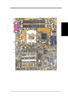
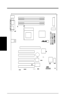
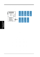
3. H/W SETUP Layout Contents 3. HARDWARE SETUP 3.2 Layout Contents Motherboard Settings 1) JEN 2) SW1 6-10 3) SW1 1-4 4) USBPWR p. 17 JumperFree Mode Setting (Disable / Enable) p. 18 CPU External Frequency (Switches 6-10) p. 20 CPU Core: Bus Frequency Multiple (Switches 1-4) p. 21 USB Device Wake-Up (Enable / Disable) Memory, CPU and Expansion 1) RIMM A1/A2/B1/B2 p. 22 184-Pin System Memory Support 2) CPU p. 24 Central Processing Unit 3) Heatsink p. 25 CPU Heatsink Retention Module Installation 3) PCI 1/2/3/4/5 p. 27 32-bit PCI Bus Expansion Slots 4) AGP Pro p. 29 Accelerated Graphics Port Slot Connectors 1) PS2KBMS p. 30 PS/2 Mouse Port (6 pin female) 2) PS2KBMS p. 30 PS/2 Keyboard Port (6 pin female) 3) PRINTER p. 31 Parallel Port (25 pin female) 4) COM1/COM2 p. 31 Serial Ports (9 pin /10-1 pin male) 5) USB p. 31 Universal Serial Bus Ports 1 & 2 (Two 4 pin female) 6) RJ45 p. 32 Fast Ethernet Port Connector (Optional) 7) PRIMARY/SECONDARY IDE p. 32 Primary and Secondary IDE Connectors (Two 40-1 pin) 8) FLOPPY p. 33 Floppy Disk Drive Connector (34 pin) 9) CPU/PCI/MAIN_FAN p. 33 CPU, PCI, and Main Fan Connectors (Three 3 pin) 10) SMB p. 34 SMBus Connector (5-1 pin) 11) CHASSIS p. 34 Chassis Intrusion Lead (2 pin) 12) WOL p. 35 Wake-On-LAN Connector (13 pin) 13) WOR p. 35 Wake-On-Ring Connector (2 pin) 14) USB2 p. 36 USB Header (10-1 pin) 15) HDDLED p. 36 Hard Disk Drive Activity LED Connector (2 pin) 16) SCSILED p. 36 SCSI Activity LED Connector (2 pin) 17) IR p. 37 Infrared Module Connector (5 pin) 18) TR2 p. 37 Device Thermal Sensor Connector (2 pin) 19) ATXPWR, AUXPWR, p. 38 ATX Power Supply Connectors (20 pin) ATX12V 20) PWR.LED (PANEL) p. 39 System Power LED Lead (3 pin) 21) KEYLOCK (PANEL) p. 39 System Keyboard Lock Switch Lead (2 pin) 22) SPEAKER (PANEL) p. 39 System Warning Speaker Lead (4 pin) 23) MSG.LED (PANEL) p. 39 System Message LED Lead (2 pin) 24) SMI (PANEL) p. 39 System Management Interrupt Lead (2 pin) 25) PWRSW (PANEL) p. 39 ATX / Soft-Off Switch Lead (2 pin) 26) RESET (PANEL) p. 39 Reset Switch Lead (2 pin) ASUS P4T User's Manual 15
-
 1
1 -
2
-
3
-
4
-
5
-
6
-
7
-
8
-
9
-
 10
10 -
 11
11 -
 12
12 -
 13
13 -
 14
14 -
 15
15 -
 16
16 -
 17
17 -
 18
18 -
 19
19 -
 20
20 -
21
-
22
-
23
-
24
-
25
-
26
-
27
-
28
-
29
-
30
-
31
-
32
-
33
-
34
-
35
-
36
-
37
-
38
-
39
-
40
-
41
-
42
-
43
-
44
-
45
-
46
-
47
-
48
-
49
-
50
-
51
-
52
-
53
-
54
-
55
-
56
-
57
-
58
-
59
-
60
-
61
-
62
-
63
-
64
-
65
-
66
-
67
-
68
-
69
-
70
-
71
-
72
-
73
-
74
-
75
-
76
-
77
-
78
-
79
-
80
-
81
-
82
-
83
-
84
-
85
-
86
-
87
-
88
-
89
-
90
-
91
-
92
-
93
-
94
-
95
-
96
-
97
-
98
-
99
-
100
-
101
-
102
-
103
-
104
-
105
-
106
-
107
-
108
-
109
-
110
-
111
-
112
-
113
-
114
-
115
-
116
 |
 |
