Asus P4T P4T User Manual - Page 36
ASUS P4T User's Manual, USB Headers 10-1 pin USB2, Hard Disk Drive Activity LED 2-pin HDDLED, SCSI
 |
View all Asus P4T manuals
Add to My Manuals
Save this manual to your list of manuals |
Page 36 highlights
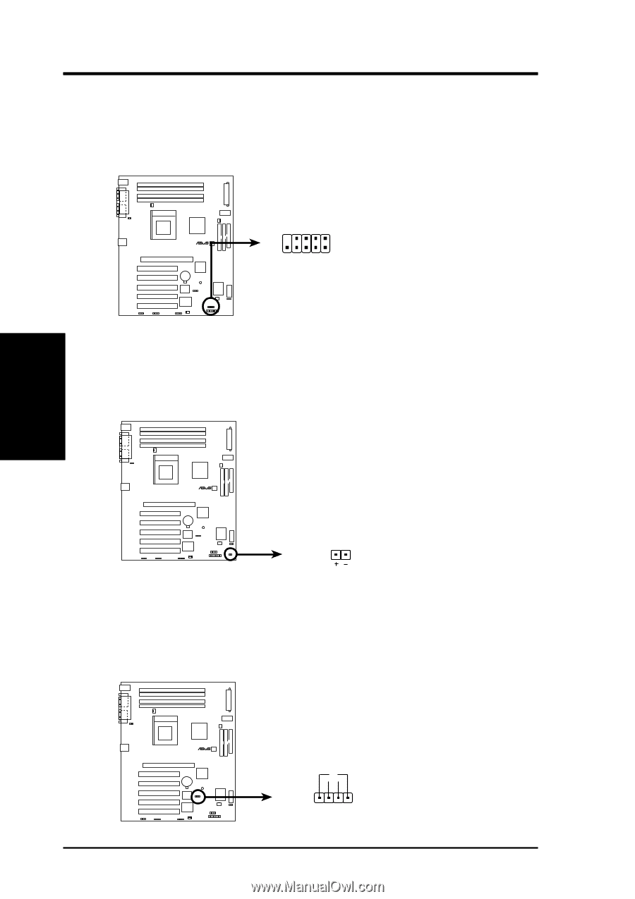
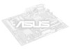
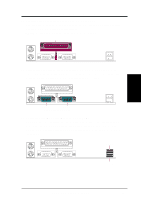
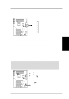
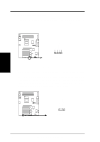
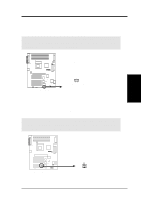
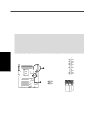
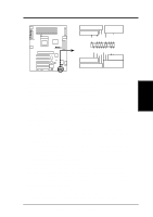
3. HARDWARE SETUP 14) USB Headers (10-1 pin USB2) If the USB Ports on the back panels are inadequate, a USB header is available for two additional USB ports. Connect the 10-1 pin ribbon cable from the provided 2-port USB connector set to the midboard 10-1 pin USB header and mount the USB connector set to an open slot on your chassis. 10 6 1: USB Power 6: USB Power 2: USBP2- 7: USBP3- ® 3: USBP2+ 8: USBP3+ 5 1 4: GND 9: GND 5: NC USB2 P4T P4T USB Headers 15) Hard Disk Drive Activity LED (2-pin HDDLED) This lead supplies power to the cabinet's hard disk drive activity LED. Read and write activity by devices connected to the Primary/Secondary IDE connectors will cause the LED to light up. 3. H/W SETUP Connectors ® P4T P4T Hard Disk Drive Activity LED TIP: If the case-mounted LED does not light, try reversing the 2-pin plug. HDDLED 16) SCSI Activity LED Lead (2-pin SCSILED) To use the Hard Disk Drive Activity LED indicator with a SCSI device connected to an add-in PCI SCSI card, connect the 4-pin connector on the PCI SCSI card to this lead. When connected, the cabinet's IDE activity LED will indicate activity of the SCSI device. ® P4T P4T SCSI LED Connector + 1 SCSILED 36 ASUS P4T User's Manual
-
 1
1 -
2
-
3
-
4
-
5
-
6
-
7
-
8
-
9
-
10
-
11
-
12
-
13
-
14
-
15
-
16
-
17
-
18
-
19
-
20
-
21
-
22
-
23
-
24
-
25
-
26
-
27
-
28
-
29
-
30
-
 31
31 -
 32
32 -
 33
33 -
 34
34 -
 35
35 -
 36
36 -
 37
37 -
 38
38 -
 39
39 -
 40
40 -
 41
41 -
42
-
43
-
44
-
45
-
46
-
47
-
48
-
49
-
50
-
51
-
52
-
53
-
54
-
55
-
56
-
57
-
58
-
59
-
60
-
61
-
62
-
63
-
64
-
65
-
66
-
67
-
68
-
69
-
70
-
71
-
72
-
73
-
74
-
75
-
76
-
77
-
78
-
79
-
80
-
81
-
82
-
83
-
84
-
85
-
86
-
87
-
88
-
89
-
90
-
91
-
92
-
93
-
94
-
95
-
96
-
97
-
98
-
99
-
100
-
101
-
102
-
103
-
104
-
105
-
106
-
107
-
108
-
109
-
110
-
111
-
112
-
113
-
114
-
115
-
116
 |
 |