Asus P4T P4T User Manual - Page 34
ASUS P4T User's Manual, SMB Connector 5-1 pin SMB, Chassis Intrusion Lead 4-1 pin CHASSIS
 |
View all Asus P4T manuals
Add to My Manuals
Save this manual to your list of manuals |
Page 34 highlights
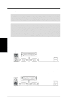
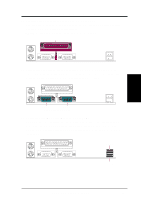
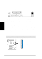
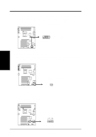
3. H/W SETUP Connectors 3. HARDWARE SETUP 10) SMB Connector (5-1 pin SMB) This connector allows you to connect SMBus (System Management Bus) devices. SMBus devices communicate by means of the SMBus with an SMBus host and/or other SMBus devices. SMBus is a specific implementation of an I2C bus, which is a multi-device bus; that is, multiple chips can be connected to the same bus and each one can act as a master by initiating data transfer. SMBCLK Ground SMBDATA +5V ® P4T P4T SMBus Connector 1 SMB 11) Chassis Intrusion Lead (4-1 pin CHASSIS) This lead is for a chassis designed for chassis intrusion detection. After-market toggle switches may also be installed to the chassis panel or on any removable components. Two wires should be available from the chassis to connect to this lead. When any chassis component is removed, the contact should open and the motherboard will record a chassis intrusion event. The event can then be processed by software such as LDCM. If the chassis intrusion lead is not used, a jumper cap must be placed over the pins to close the circuit. +5VSB_MB Chassis Signal GND ® P4T P4T Chassis Open Alarm Lead 1 CHASSIS 34 ASUS P4T User's Manual
-
 1
1 -
2
-
3
-
4
-
5
-
6
-
7
-
8
-
9
-
10
-
11
-
12
-
13
-
14
-
15
-
16
-
17
-
18
-
19
-
20
-
21
-
22
-
23
-
24
-
25
-
26
-
27
-
28
-
 29
29 -
 30
30 -
 31
31 -
 32
32 -
 33
33 -
 34
34 -
 35
35 -
 36
36 -
 37
37 -
 38
38 -
 39
39 -
40
-
41
-
42
-
43
-
44
-
45
-
46
-
47
-
48
-
49
-
50
-
51
-
52
-
53
-
54
-
55
-
56
-
57
-
58
-
59
-
60
-
61
-
62
-
63
-
64
-
65
-
66
-
67
-
68
-
69
-
70
-
71
-
72
-
73
-
74
-
75
-
76
-
77
-
78
-
79
-
80
-
81
-
82
-
83
-
84
-
85
-
86
-
87
-
88
-
89
-
90
-
91
-
92
-
93
-
94
-
95
-
96
-
97
-
98
-
99
-
100
-
101
-
102
-
103
-
104
-
105
-
106
-
107
-
108
-
109
-
110
-
111
-
112
-
113
-
114
-
115
-
116
 |
 |
