Asus P4T P4T User Manual - Page 23
Installing Memory
 |
View all Asus P4T manuals
Add to My Manuals
Save this manual to your list of manuals |
Page 23 highlights
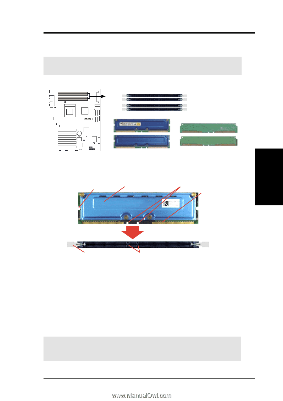
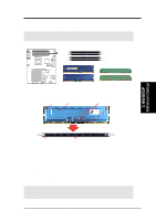
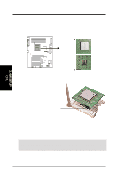
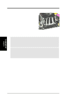
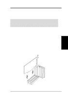
3. HARDWARE SETUP 3.5.1 Installing Memory The memory module (RIMM / C-RIMM) will fit in only one orientation. IMPORTANT: Do not touch the memory module's connectors. Handle the module only by the edges. Channel B Channel A ® RIMM Sockets RIMMB2 RIMMB1 RIMMA2 RIMMA1 P4T P4T 184-Pin RIMM Sockets RIMM with Heat Spreader C-RIMM 1. Make sure that the notch keys in the module are aligned with the small ribs inside the RIMM sockets. MOUNTING NOTCH RDRAM (with heat spreader) NOTCH KEYS CONNECTORS 3. H/W SETUP Motherboard Settings EJECTOR RIBS (inside socket) (TOP VIEW) 2. With the ejectors in the open position (as shown), push down gently but firmly on the memory module until it snaps into place. The guides on the socket's ejectors should go through the two mounting notches on the module and the ejectors should close. If necessary, push the ejectors inward to secure the module in place. Removing Memory To release a memory module, push both ejectors outward and pull the module straight up and out of the RIMM sockets. WARNING! RIMM modules become extremely hot during operation. To reduce the risk of personal injury from hot surfaces, allow the modules to cool off before removing them. ASUS P4T User's Manual 23
-
 1
1 -
2
-
3
-
4
-
5
-
6
-
7
-
8
-
9
-
10
-
11
-
12
-
13
-
14
-
15
-
16
-
17
-
 18
18 -
 19
19 -
 20
20 -
 21
21 -
 22
22 -
 23
23 -
 24
24 -
 25
25 -
 26
26 -
 27
27 -
 28
28 -
29
-
30
-
31
-
32
-
33
-
34
-
35
-
36
-
37
-
38
-
39
-
40
-
41
-
42
-
43
-
44
-
45
-
46
-
47
-
48
-
49
-
50
-
51
-
52
-
53
-
54
-
55
-
56
-
57
-
58
-
59
-
60
-
61
-
62
-
63
-
64
-
65
-
66
-
67
-
68
-
69
-
70
-
71
-
72
-
73
-
74
-
75
-
76
-
77
-
78
-
79
-
80
-
81
-
82
-
83
-
84
-
85
-
86
-
87
-
88
-
89
-
90
-
91
-
92
-
93
-
94
-
95
-
96
-
97
-
98
-
99
-
100
-
101
-
102
-
103
-
104
-
105
-
106
-
107
-
108
-
109
-
110
-
111
-
112
-
113
-
114
-
115
-
116
 |
 |