Asus P4T P4T User Manual - Page 37
ASUS P4T User's Manual, Infrared Module Connector 5-pin IR, Device Thermal Sensor Connector 2-pin
 |
View all Asus P4T manuals
Add to My Manuals
Save this manual to your list of manuals |
Page 37 highlights
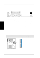
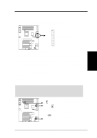
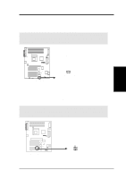
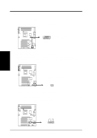
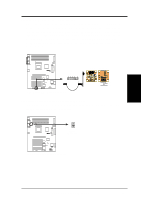
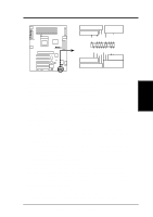
+5V (NC) IRRX GND IRTX 3. H/W SETUP Connectors 3. HARDWARE SETUP 17) Infrared Module Connector (5-pin IR) This connector supports an optional wireless transmitting and receiving infrared module. This module mounts to a small opening on system cases that support this feature. You must also configure the setting through UART2 Use Infrared (see 4.4.2 I/O device Configuration) to select whether UART2 is directed for use with COM2 or IrDA. Use the five pins as shown in Back View and connect a ribben cable from the module to the motherboard's IR connector according to the pin definitions. Front View Back View IR ® 1 P4T P4T Infrared Module Connector IRTX +5V GND (NC) IRRX 18) Device Thermal Sensor Connector (2-pin TR2) If you have a device (e.g. power supply) with thermal monitoring, connect its thermal sensor cable to this connector. TR2 Thermal Sensor ® Connector P4T P4T Thermal Sensor Connector ASUS P4T User's Manual 37
-
 1
1 -
2
-
3
-
4
-
5
-
6
-
7
-
8
-
9
-
10
-
11
-
12
-
13
-
14
-
15
-
16
-
17
-
18
-
19
-
20
-
21
-
22
-
23
-
24
-
25
-
26
-
27
-
28
-
29
-
30
-
31
-
 32
32 -
 33
33 -
 34
34 -
 35
35 -
 36
36 -
 37
37 -
 38
38 -
 39
39 -
 40
40 -
 41
41 -
 42
42 -
43
-
44
-
45
-
46
-
47
-
48
-
49
-
50
-
51
-
52
-
53
-
54
-
55
-
56
-
57
-
58
-
59
-
60
-
61
-
62
-
63
-
64
-
65
-
66
-
67
-
68
-
69
-
70
-
71
-
72
-
73
-
74
-
75
-
76
-
77
-
78
-
79
-
80
-
81
-
82
-
83
-
84
-
85
-
86
-
87
-
88
-
89
-
90
-
91
-
92
-
93
-
94
-
95
-
96
-
97
-
98
-
99
-
100
-
101
-
102
-
103
-
104
-
105
-
106
-
107
-
108
-
109
-
110
-
111
-
112
-
113
-
114
-
115
-
116
 |
 |
