Asus P4T P4T User Manual - Page 38
ASUS P4T User's Manual, Power Supply Connectors, pin block ATXPWR, pin AUXPWR, pin ATX12V
 |
View all Asus P4T manuals
Add to My Manuals
Save this manual to your list of manuals |
Page 38 highlights
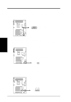
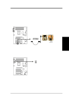
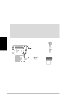
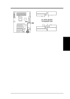
3. HARDWARE SETUP 19) Power Supply Connectors (20-pin block ATXPWR) (6-pin AUXPWR) (4-pin ATX12V) These connectors connect to an ATX 12V power supply. Each plug from the power supply will only insert in one orientation because of the different hole sizes. Find the proper orientation and push down firmly making sure that the pins are aligned. An auxiliary power supply may be needed depending on your system configuration. IMPORTANT: Make sure that your ATX 12V power supply (minimum recommended wattage: 230 watts; 300W for a fully-configured system) can supply at least 20 amperes on the +5-volt lead and at least 720mA on the +5-volt standby lead (+5VSB). Your system may become unstable/unreliable and may experience difficulty in powering up if your power supply is inadequate. For WakeOn-LAN support, your ATX power supply (minimum recommended wattage: 230watts) must supply at least 720mA +5VSB. ATXPWR Pin 1 +12.0VDC +5VSB PWR_OK COM +5.0VDC COM +5.0VDC COM +3.3VDC +3.3VDC +5.0VDC +5.0VDC -5.0VDC COM COM COM PS_ON# COM -12.0VDC +3.3VDC ® P4T P4T ATX & Auxiliary Power Connectors Pin 1 COM COM Pin 1 +12V DC +12V DC Key ATX12V COM +3V +5V AUXPWR 3. H/W SETUP Connectors 38 ASUS P4T User's Manual
-
 1
1 -
2
-
3
-
4
-
5
-
6
-
7
-
8
-
9
-
10
-
11
-
12
-
13
-
14
-
15
-
16
-
17
-
18
-
19
-
20
-
21
-
22
-
23
-
24
-
25
-
26
-
27
-
28
-
29
-
30
-
31
-
32
-
 33
33 -
 34
34 -
 35
35 -
 36
36 -
 37
37 -
 38
38 -
 39
39 -
 40
40 -
 41
41 -
 42
42 -
 43
43 -
44
-
45
-
46
-
47
-
48
-
49
-
50
-
51
-
52
-
53
-
54
-
55
-
56
-
57
-
58
-
59
-
60
-
61
-
62
-
63
-
64
-
65
-
66
-
67
-
68
-
69
-
70
-
71
-
72
-
73
-
74
-
75
-
76
-
77
-
78
-
79
-
80
-
81
-
82
-
83
-
84
-
85
-
86
-
87
-
88
-
89
-
90
-
91
-
92
-
93
-
94
-
95
-
96
-
97
-
98
-
99
-
100
-
101
-
102
-
103
-
104
-
105
-
106
-
107
-
108
-
109
-
110
-
111
-
112
-
113
-
114
-
115
-
116
 |
 |
